📐 Grid Modelling
Three-phase AC systems dominate power transmission and distribution for their efficiency, capacity, and compatibility. While ideal systems are balanced and suitable for positive-sequence analysis, real networks often experience asymmetries from untransposed lines, uneven loads, single-phase connections, and converter-based resources. The classical symmetrical components method simplifies unbalanced fault analysis but struggles with strong sequence coupling, non-linearities, and complex topologies.
Direct phase-domain (abc) modelling overcomes these limitations by representing actual phase quantities, naturally handling asymmetry, non-linearities, and all fault types. It is particularly suited for transient simulations, EMTP tools, and control design across all voltage levels.
Power systems comprise generators, transformers, lines, loads, and compensation equipment, interconnected from generation through transmission and distribution to end users. Transmission operates at high voltages to reduce losses, with transformers stepping voltages up or down as required. Transmission circuits often include series and shunt compensation, while transformer winding configurations must be carefully modelled under unbalanced conditions. At the distribution level, load points can be highly unbalanced due to single-phase connections.

Bus
A Bus is the main electrical node in MultiCircuit. It holds voltage state variables and anchors injections, branch terminals, and operational limits.
This device belongs to the electrical topology and location hierarchy managed directly by MultiCircuit.
Registered properties
Profile-enabled properties: active, Vmin, Vmax.
name |
class_type |
unit |
mandatory |
max_chars |
descriptions |
has_profile |
comment |
|---|---|---|---|---|---|---|---|
idtag |
str |
False |
Unique ID |
False |
|||
name |
str |
False |
Name of the device. |
False |
|||
code |
str |
False |
Secondary ID |
False |
|||
rdfid |
str |
False |
RDF ID for further compatibility |
False |
|||
action |
enum ActionType |
False |
Object action to perform. Only used for model merging. |
False |
|||
comment |
str |
False |
User comment |
False |
|||
diff_changes |
MergeInformation |
False |
False |
||||
modelling_authority |
Modelling Authority |
False |
Modelling authority of this asset |
False |
|||
commissioned_date |
int |
False |
Commissioned date of the asset |
False |
|||
decommissioned_date |
int |
False |
Decommissioned date of the asset |
False |
|||
build_status |
enum BuildStatus |
False |
Device build status. Used in expansion planning. |
False |
|||
owners |
AssociationsList |
p.u. |
False |
Owners associations to injections |
False |
||
rms_model |
DaeBlock |
False |
RMS dynamic model |
False |
|||
emt_model |
DaeBlock |
False |
EMT dynamic model |
False |
|||
active |
bool |
False |
Is the bus active? used to disable the bus. |
True |
|||
is_slack |
bool |
False |
Force the bus to be of slack type. |
False |
|||
is_dc |
bool |
False |
Is this bus of DC type?. |
False |
|||
is_grounded |
bool |
False |
Is this bus connected to ground?. |
False |
|||
graphic_type |
enum BusGraphicType |
False |
Graphic to use in the schematic. |
False |
|||
Vnom |
float |
kV |
False |
Nominal line voltage of the bus. |
False |
||
Vm0 |
float |
p.u. |
False |
Voltage module guess. |
False |
||
Va0 |
float |
rad. |
False |
Voltage angle guess. |
False |
||
Vmin |
float |
p.u. |
False |
Lower range of allowed voltage module. |
True |
||
Vmax |
float |
p.u. |
False |
Higher range of allowed voltage module. |
True |
||
Vm_cost |
float |
e/unit |
False |
Cost of over and under voltages |
False |
||
angle_min |
float |
rad. |
False |
Lower range of allowed voltage angle. |
False |
||
angle_max |
float |
rad. |
False |
Higher range of allowed voltage angle. |
False |
||
angle_cost |
float |
e/unit |
False |
Cost of over and under angles |
False |
||
x |
float |
px |
False |
x position in pixels. |
False |
||
y |
float |
px |
False |
y position in pixels. |
False |
||
h |
float |
px |
False |
height of the bus in pixels. |
False |
||
w |
float |
px |
False |
Width of the bus in pixels. |
False |
||
country |
Country |
False |
Country of the bus |
False |
|||
area |
Area |
False |
Area of the bus |
False |
|||
zone |
Zone |
False |
Zone of the bus |
False |
|||
substation |
Substation |
False |
Substation of the bus. |
False |
|||
voltage_level |
Voltage level |
False |
Voltage level of the bus. |
False |
|||
bus_bar |
BusBar |
False |
Busbar associated to the bus. |
False |
|||
longitude |
float |
deg |
False |
longitude of the bus. |
False |
||
latitude |
float |
deg |
False |
latitude of the bus. |
False |
||
color |
str |
False |
Color to paint the element in the diagram |
False |
BusBar
A BusBar represents an explicit busbar object inside a voltage level. It is useful when diagram structure or substation-level topology needs to be preserved.
This device belongs to the electrical topology and location hierarchy managed directly by MultiCircuit.
Registered properties
Profile-enabled properties: none.
name |
class_type |
unit |
mandatory |
max_chars |
descriptions |
has_profile |
comment |
|---|---|---|---|---|---|---|---|
idtag |
str |
False |
Unique ID |
False |
|||
name |
str |
False |
Name of the device. |
False |
|||
code |
str |
False |
Secondary ID |
False |
|||
rdfid |
str |
False |
RDF ID for further compatibility |
False |
|||
action |
enum ActionType |
False |
Object action to perform. Only used for model merging. |
False |
|||
comment |
str |
False |
User comment |
False |
|||
diff_changes |
MergeInformation |
False |
False |
||||
modelling_authority |
Modelling Authority |
False |
Modelling authority of this asset |
False |
|||
commissioned_date |
int |
False |
Commissioned date of the asset |
False |
|||
decommissioned_date |
int |
False |
Decommissioned date of the asset |
False |
|||
build_status |
enum BuildStatus |
False |
Device build status. Used in expansion planning. |
False |
|||
owners |
AssociationsList |
p.u. |
False |
Owners associations to injections |
False |
||
voltage_level |
Bus |
False |
Voltage level of this BusBar |
False |
VoltageLevel
A VoltageLevel groups buses and busbars that belong to the same nominal voltage inside a substation.
This device belongs to the electrical topology and location hierarchy managed directly by MultiCircuit.
Registered properties
Profile-enabled properties: none.
name |
class_type |
unit |
mandatory |
max_chars |
descriptions |
has_profile |
comment |
|---|---|---|---|---|---|---|---|
idtag |
str |
False |
Unique ID |
False |
|||
name |
str |
False |
Name of the device. |
False |
|||
code |
str |
False |
Secondary ID |
False |
|||
rdfid |
str |
False |
RDF ID for further compatibility |
False |
|||
action |
enum ActionType |
False |
Object action to perform. Only used for model merging. |
False |
|||
comment |
str |
False |
User comment |
False |
|||
diff_changes |
MergeInformation |
False |
False |
||||
modelling_authority |
Modelling Authority |
False |
Modelling authority of this asset |
False |
|||
commissioned_date |
int |
False |
Commissioned date of the asset |
False |
|||
decommissioned_date |
int |
False |
Decommissioned date of the asset |
False |
|||
build_status |
enum BuildStatus |
False |
Device build status. Used in expansion planning. |
False |
|||
owners |
AssociationsList |
p.u. |
False |
Owners associations to injections |
False |
||
Vnom |
float |
kV |
False |
Nominal voltage |
False |
||
substation |
Substation |
False |
Substation of this Voltage level (optional) |
False |
Substation
A Substation is the top-level station object used to group voltage levels, buses, and related physical assets.
This device belongs to the electrical topology and location hierarchy managed directly by MultiCircuit.
Registered properties
Profile-enabled properties: irradiation, temperature, wind_speed.
name |
class_type |
unit |
mandatory |
max_chars |
descriptions |
has_profile |
comment |
|---|---|---|---|---|---|---|---|
idtag |
str |
False |
Unique ID |
False |
|||
name |
str |
False |
Name of the device. |
False |
|||
code |
str |
False |
Secondary ID |
False |
|||
rdfid |
str |
False |
RDF ID for further compatibility |
False |
|||
action |
enum ActionType |
False |
Object action to perform. Only used for model merging. |
False |
|||
comment |
str |
False |
User comment |
False |
|||
diff_changes |
MergeInformation |
False |
False |
||||
modelling_authority |
Modelling Authority |
False |
Modelling authority of this asset |
False |
|||
commissioned_date |
int |
False |
Commissioned date of the asset |
False |
|||
decommissioned_date |
int |
False |
Decommissioned date of the asset |
False |
|||
build_status |
enum BuildStatus |
False |
Device build status. Used in expansion planning. |
False |
|||
owners |
AssociationsList |
p.u. |
False |
Owners associations to injections |
False |
||
longitude |
float |
deg |
False |
longitude. |
False |
||
latitude |
float |
deg |
False |
latitude. |
False |
||
color |
str |
False |
Color to paint the element in the map diagram |
False |
|||
area |
Area |
False |
Substation area, alternatively this can be obtained from the zone |
False |
|||
zone |
Zone |
False |
Substation area |
False |
|||
country |
Country |
False |
Substation country, alternatively this can be obtained from the community |
False |
|||
community |
Community |
False |
Substation community, alternatively this can be obtained from the region |
False |
|||
region |
Region |
False |
Substation region, alternatively this can be obtained from the municipality |
False |
|||
municipality |
Municipality |
False |
Substation municipality |
False |
|||
address |
str |
False |
Substation address |
False |
|||
irradiation |
float |
W/m^2 |
False |
Substation solar irradiation |
True |
||
temperature |
float |
ºC |
False |
Substation temperature |
True |
||
wind_speed |
float |
m/s |
False |
Substation wind speed at 80m above the ground |
True |
||
terrain_roughness |
float |
False |
This value is ised for wind speed extrapolation. Typical values: Not rough (sand, snow, sea): 0~0.02 Slightly rough (grass, cereal field): 0.02~0.2 Rough (forest, small houses): 1.0~1.5 Very rough (Large buildings):1.0~4.0 |
False |
Country
A Country groups assets at country scope for reporting, filtering, transfer-capacity studies, and geographic organization.
This device provides geographical or administrative context for topology and reporting.
Registered properties
Profile-enabled properties: none.
name |
class_type |
unit |
mandatory |
max_chars |
descriptions |
has_profile |
comment |
|---|---|---|---|---|---|---|---|
idtag |
str |
False |
Unique ID |
False |
|||
name |
str |
False |
Name of the device. |
False |
|||
code |
str |
False |
Secondary ID |
False |
|||
rdfid |
str |
False |
RDF ID for further compatibility |
False |
|||
action |
enum ActionType |
False |
Object action to perform. Only used for model merging. |
False |
|||
comment |
str |
False |
User comment |
False |
|||
diff_changes |
MergeInformation |
False |
False |
||||
longitude |
float |
deg |
False |
longitude. |
False |
||
latitude |
float |
deg |
False |
latitude. |
False |
||
color |
str |
False |
Color to paint the element in the map diagram |
False |
Community
A Community is an intermediate regional grouping that can be attached to buses and inherited by connected assets.
This device provides geographical or administrative context for topology and reporting.
Registered properties
Profile-enabled properties: none.
name |
class_type |
unit |
mandatory |
max_chars |
descriptions |
has_profile |
comment |
|---|---|---|---|---|---|---|---|
idtag |
str |
False |
Unique ID |
False |
|||
name |
str |
False |
Name of the device. |
False |
|||
code |
str |
False |
Secondary ID |
False |
|||
rdfid |
str |
False |
RDF ID for further compatibility |
False |
|||
action |
enum ActionType |
False |
Object action to perform. Only used for model merging. |
False |
|||
comment |
str |
False |
User comment |
False |
|||
diff_changes |
MergeInformation |
False |
False |
||||
longitude |
float |
deg |
False |
longitude. |
False |
||
latitude |
float |
deg |
False |
latitude. |
False |
||
color |
str |
False |
Color to paint the element in the map diagram |
False |
|||
country |
Country |
False |
Substation country, altenativelly this can be obtained from the community |
False |
Region
A Region groups substations and buses below the community level and above municipalities.
This device provides geographical or administrative context for topology and reporting.
Registered properties
Profile-enabled properties: none.
name |
class_type |
unit |
mandatory |
max_chars |
descriptions |
has_profile |
comment |
|---|---|---|---|---|---|---|---|
idtag |
str |
False |
Unique ID |
False |
|||
name |
str |
False |
Name of the device. |
False |
|||
code |
str |
False |
Secondary ID |
False |
|||
rdfid |
str |
False |
RDF ID for further compatibility |
False |
|||
action |
enum ActionType |
False |
Object action to perform. Only used for model merging. |
False |
|||
comment |
str |
False |
User comment |
False |
|||
diff_changes |
MergeInformation |
False |
False |
||||
longitude |
float |
deg |
False |
longitude. |
False |
||
latitude |
float |
deg |
False |
latitude. |
False |
||
color |
str |
False |
Color to paint the element in the map diagram |
False |
|||
community |
Community |
False |
Substation community, altenativelly this can be obtained from the region |
False |
Municipality
A Municipality stores local administrative context for buses and substations.
This device provides geographical or administrative context for topology and reporting.
Registered properties
Profile-enabled properties: none.
name |
class_type |
unit |
mandatory |
max_chars |
descriptions |
has_profile |
comment |
|---|---|---|---|---|---|---|---|
idtag |
str |
False |
Unique ID |
False |
|||
name |
str |
False |
Name of the device. |
False |
|||
code |
str |
False |
Secondary ID |
False |
|||
rdfid |
str |
False |
RDF ID for further compatibility |
False |
|||
action |
enum ActionType |
False |
Object action to perform. Only used for model merging. |
False |
|||
comment |
str |
False |
User comment |
False |
|||
diff_changes |
MergeInformation |
False |
False |
||||
longitude |
float |
deg |
False |
longitude. |
False |
||
latitude |
float |
deg |
False |
latitude. |
False |
||
color |
str |
False |
Color to paint the element in the map diagram |
False |
|||
region |
Region |
False |
Substation region, alternatively this can be obtained from the municipality |
False |
Area
An Area groups buses for operational aggregation and transfer-capacity workflows.
This device provides geographical or administrative context for topology and reporting.
Registered properties
Profile-enabled properties: none.
name |
class_type |
unit |
mandatory |
max_chars |
descriptions |
has_profile |
comment |
|---|---|---|---|---|---|---|---|
idtag |
str |
False |
Unique ID |
False |
|||
name |
str |
False |
Name of the device. |
False |
|||
code |
str |
False |
Secondary ID |
False |
|||
rdfid |
str |
False |
RDF ID for further compatibility |
False |
|||
action |
enum ActionType |
False |
Object action to perform. Only used for model merging. |
False |
|||
comment |
str |
False |
User comment |
False |
|||
diff_changes |
MergeInformation |
False |
False |
||||
longitude |
float |
deg |
False |
longitude. |
False |
||
latitude |
float |
deg |
False |
latitude. |
False |
||
color |
str |
False |
Color to paint the element in the map diagram |
False |
Zone
A Zone is a market or study grouping used to aggregate buses and branches.
This device provides geographical or administrative context for topology and reporting.
Registered properties
Profile-enabled properties: none.
name |
class_type |
unit |
mandatory |
max_chars |
descriptions |
has_profile |
comment |
|---|---|---|---|---|---|---|---|
idtag |
str |
False |
Unique ID |
False |
|||
name |
str |
False |
Name of the device. |
False |
|||
code |
str |
False |
Secondary ID |
False |
|||
rdfid |
str |
False |
RDF ID for further compatibility |
False |
|||
action |
enum ActionType |
False |
Object action to perform. Only used for model merging. |
False |
|||
comment |
str |
False |
User comment |
False |
|||
diff_changes |
MergeInformation |
False |
False |
||||
longitude |
float |
deg |
False |
longitude. |
False |
||
latitude |
float |
deg |
False |
latitude. |
False |
||
color |
str |
False |
Color to paint the element in the map diagram |
False |
|||
area |
Area |
False |
Area of this zone. |
False |
Generator
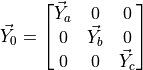
For the power flow simulations, generators had been modelled as simple power injections into the system, which was
completely valid. However, this is not sufficient when performing the short-circuit analysis, as the impedance of the
generator must also be taken into account. VeraGrid has been programmed to accept a  impedance matrix, which
includes both the self and mutual impedances between the
impedance matrix, which
includes both the self and mutual impedances between the  phases.
It is also common to encounter generator impedances in the sequence domain. Therefore, Fortescue’s theorem is applied to obtain the equivalent values for the three phases:
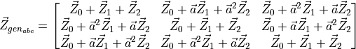
Where the transformation eigenvector  is used.
The generator could be modelled during the short-circuit using the classic Thévenin equivalent, that is, as an ideal voltage source in series with the generator’s impedance, as shown in the electrical circuit of the following figure:

However, this would require to add an additional bus to the original system between the generator’s impedance and the ideal voltage source. Therefore, the generator can be also modelled using its Norton equivalent, that is, an ideal current source in parallel with the generator’s impedance, as shown in the schematic bellow:

The Norton current source will take the value of the internal voltage multiplied by its admittance:
Example
import VeraGridEngine.api as gce

logger = gce.Logger()
grid = gce.MultiCircuit()

# ----------------------------------------------------------------------------------------------------------------------
# Buses
# ----------------------------------------------------------------------------------------------------------------------
bus = gce.Bus(name='Bus', Vnom=4.16)
grid.add_bus(obj=bus)

# ----------------------------------------------------------------------------------------------------------------------
# Generator
# ----------------------------------------------------------------------------------------------------------------------
gen = gce.Generator(vset=1.0, r1=0.004, x1=0.5, r2=0.02, x2=0.5, r0=0.01, x0=0.08)
grid.add_generator(bus=bus, api_obj=gen)
Registered properties
Profile-enabled properties: active, Cost, shift_key, P, Pmin, Pmax, Q, Qmin, Qmax, Pf, Vset, Cost2, Cost0, enabled_dispatch, must_run, srap_enabled.
name |
class_type |
unit |
mandatory |
max_chars |
descriptions |
has_profile |
comment |
|---|---|---|---|---|---|---|---|
idtag |
str |
False |
Unique ID |
False |
|||
name |
str |
False |
Name of the device. |
False |
|||
code |
str |
False |
Secondary ID |
False |
|||
rdfid |
str |
False |
RDF ID for further compatibility |
False |
|||
action |
enum ActionType |
False |
Object action to perform. Only used for model merging. |
False |
|||
comment |
str |
False |
User comment |
False |
|||
diff_changes |
MergeInformation |
False |
False |
||||
modelling_authority |
Modelling Authority |
False |
Modelling authority of this asset |
False |
|||
commissioned_date |
int |
False |
Commissioned date of the asset |
False |
|||
decommissioned_date |
int |
False |
Decommissioned date of the asset |
False |
|||
build_status |
enum BuildStatus |
False |
Device build status. Used in expansion planning. |
False |
|||
owners |
AssociationsList |
p.u. |
False |
Owners associations to injections |
False |
||
rms_model |
DaeBlock |
False |
RMS dynamic model |
False |
|||
emt_model |
DaeBlock |
False |
EMT dynamic model |
False |
|||
rms_template |
RMS template |
False |
Native RMS template used. Assigning it clears rms_fmu_template. |
False |
|||
emt_template |
EMT template |
False |
Native EMT template used. Assigning it clears emt_fmu_template. |
False |
|||
rms_fmu_template |
FMU template |
False |
RMS FMU template used only by RMS simulations. Assigning it clears rms_template. |
False |
|||
emt_fmu_template |
FMU template |
False |
EMT FMU template used only by EMT simulations. Assigning it clears emt_template. |
False |
|||
rms_fmu_import_config |
str |
False |
Serialized FMU Co-Simulation RMS configuration |
False |
|||
emt_fmu_import_config |
str |
False |
Serialized FMU Co-Simulation EMT configuration |
False |
|||
rms_fmu_me_import_config |
str |
False |
Serialized FMU Model Exchange RMS configuration |
False |
|||
emt_fmu_me_import_config |
str |
False |
Serialized FMU Model Exchange EMT configuration |
False |
|||
bus |
Bus |
False |
Connection bus |
False |
|||
active |
bool |
False |
Is the load active? |
True |
|||
color |
str |
False |
Color to paint the element in the map diagram |
False |
|||
mttf |
float |
h |
False |
Mean time to failure |
False |
||
mttr |
float |
h |
False |
Mean time to recovery |
False |
||
capex |
float |
e/MW |
False |
Cost of investment. Used in expansion planning. |
False |
||
opex |
float |
e/MWh |
False |
Cost of operation. Used in expansion planning. |
False |
||
Cost |
float |
e/MWh |
False |
Cost of not served energy. Used in OPF. |
True |
||
facility |
Facility |
False |
Facility where this is located |
False |
|||
technologies |
AssociationsList |
p.u. |
False |
Technologies associations to injections |
False |
||
scalable |
bool |
False |
Is the injection scalable? |
False |
|||
shift_key |
float |
False |
Shift key for net transfer capacity |
True |
|||
longitude |
float |
deg |
False |
longitude of the injection. |
False |
||
latitude |
float |
deg |
False |
latitude of the injection. |
False |
||
use_kw |
bool |
False |
Consider the injections in kW and kVAr? |
False |
|||
conn |
enum ShuntConnectionType |
False |
Connection type for 3-phase studies |
False |
|||
bus_pos |
int |
False |
Aid to locate devices on a busbar |
False |
|||
P |
float |
MW |
False |
Active power |
True |
||
Pmin |
float |
MW |
False |
Minimum active power. Used in OPF. |
True |
||
Pmax |
float |
MW |
False |
Maximum active power. Used in OPF. |
True |
||
Q |
float |
MVAr |
False |
Reactive power |
True |
||
Qmin |
float |
MVAr |
False |
Minimum reactive power. |
True |
||
Qmax |
float |
MVAr |
False |
Maximum reactive power. |
True |
||
control_mode |
enum GeneratorControlMode |
False |
Generator control mode |
False |
|||
control_bus |
Bus |
False |
Control bus |
False |
|||
Pf |
float |
False |
Power factor (cos(phi)). This is used for non-controlled generators. |
True |
|||
Vset |
float |
p.u. |
False |
Set voltage. This is used for controlled generators. |
True |
||
k_droop |
float |
False |
QV droop constant. |
False |
|||
dead_band |
float |
kV |
False |
Droop dead band. |
False |
||
Snom |
float |
MVA |
False |
Nominal power. |
False |
||
use_reactive_power_curve |
bool |
False |
Use the reactive power capability curve? |
False |
|||
q_curve |
Generator Q curve |
MVAr |
False |
Capability curve data (double click on the generator to edit) |
False |
||
R1 |
float |
p.u. |
False |
Total positive sequence resistance. |
False |
||
X1 |
float |
p.u. |
False |
Total positive sequence reactance. |
False |
||
R0 |
float |
p.u. |
False |
Total zero sequence resistance. |
False |
||
X0 |
float |
p.u. |
False |
Total zero sequence reactance. |
False |
||
R2 |
float |
p.u. |
False |
Total negative sequence resistance. |
False |
||
X2 |
float |
p.u. |
False |
Total negative sequence reactance. |
False |
||
Rs |
float |
p.u. |
False |
Stator winding resistance (AG). |
False |
||
Xs |
float |
p.u. |
False |
Stator leakage reactance (AG). |
False |
||
Xm |
float |
p.u. |
False |
Magnetizing reactance (AG). |
False |
||
Rr |
float |
p.u. |
False |
Rotor resistance (AG). |
False |
||
Xr |
float |
p.u. |
False |
Rotor reactance (AG). |
False |
||
Cost2 |
float |
e/MW²/h |
False |
Generation quadratic cost. Used in OPF. |
True |
||
Cost0 |
float |
e/h |
False |
Generation constant cost. Used in OPF. |
True |
||
startup_cost |
float |
e/h |
False |
Generation start-up cost. Used in OPF. |
False |
||
shutdown_cost |
float |
e/h |
False |
Generation shut-down cost. Used in OPF. |
False |
||
min_time_up |
float |
h |
False |
Minimum time that the generator has to be on when started. Used in OPF. |
False |
||
min_time_down |
float |
h |
False |
Minimum time that the generator has to be off when shut down. Used in OPF. |
False |
||
ramp_up |
float |
MW/h |
False |
Maximum amount of generation increase per hour. |
False |
||
ramp_down |
float |
MW/h |
False |
Maximum amount of generation decrease per hour. |
False |
||
enabled_dispatch |
bool |
False |
Enabled for dispatch? Used in OPF. |
True |
|||
must_run |
bool |
False |
P >= Pmin constraint. Used in OPF with unit commitment active. |
True |
|||
emissions |
AssociationsList |
t/MWh |
False |
List of emissions |
False |
||
fuels |
AssociationsList |
t/MWh |
False |
List of fuels |
False |
||
srap_enabled |
bool |
False |
Is the unit available for SRAP participation? |
True |
|||
tpe |
enum GeneratorType |
False |
Machine type of the generator. |
False |
Battery
A Battery extends generator-style injection modelling with energy-capacity and state-of-charge parameters for storage studies.
This device connects to a bus and contributes power, current, or admittance to the solved network model.
Registered properties
Profile-enabled properties: active, Cost, shift_key, P, Pmin, Pmax, Q, Qmin, Qmax, Pf, Vset, Cost2, Cost0, enabled_dispatch, must_run, srap_enabled.
name |
class_type |
unit |
mandatory |
max_chars |
descriptions |
has_profile |
comment |
|---|---|---|---|---|---|---|---|
idtag |
str |
False |
Unique ID |
False |
|||
name |
str |
False |
Name of the device. |
False |
|||
code |
str |
False |
Secondary ID |
False |
|||
rdfid |
str |
False |
RDF ID for further compatibility |
False |
|||
action |
enum ActionType |
False |
Object action to perform. Only used for model merging. |
False |
|||
comment |
str |
False |
User comment |
False |
|||
diff_changes |
MergeInformation |
False |
False |
||||
modelling_authority |
Modelling Authority |
False |
Modelling authority of this asset |
False |
|||
commissioned_date |
int |
False |
Commissioned date of the asset |
False |
|||
decommissioned_date |
int |
False |
Decommissioned date of the asset |
False |
|||
build_status |
enum BuildStatus |
False |
Device build status. Used in expansion planning. |
False |
|||
owners |
AssociationsList |
p.u. |
False |
Owners associations to injections |
False |
||
rms_model |
DaeBlock |
False |
RMS dynamic model |
False |
|||
emt_model |
DaeBlock |
False |
EMT dynamic model |
False |
|||
rms_template |
RMS template |
False |
Native RMS template used. Assigning it clears rms_fmu_template. |
False |
|||
emt_template |
EMT template |
False |
Native EMT template used. Assigning it clears emt_fmu_template. |
False |
|||
rms_fmu_template |
FMU template |
False |
RMS FMU template used only by RMS simulations. Assigning it clears rms_template. |
False |
|||
emt_fmu_template |
FMU template |
False |
EMT FMU template used only by EMT simulations. Assigning it clears emt_template. |
False |
|||
rms_fmu_import_config |
str |
False |
Serialized FMU Co-Simulation RMS configuration |
False |
|||
emt_fmu_import_config |
str |
False |
Serialized FMU Co-Simulation EMT configuration |
False |
|||
rms_fmu_me_import_config |
str |
False |
Serialized FMU Model Exchange RMS configuration |
False |
|||
emt_fmu_me_import_config |
str |
False |
Serialized FMU Model Exchange EMT configuration |
False |
|||
bus |
Bus |
False |
Connection bus |
False |
|||
active |
bool |
False |
Is the load active? |
True |
|||
color |
str |
False |
Color to paint the element in the map diagram |
False |
|||
mttf |
float |
h |
False |
Mean time to failure |
False |
||
mttr |
float |
h |
False |
Mean time to recovery |
False |
||
capex |
float |
e/MW |
False |
Cost of investment. Used in expansion planning. |
False |
||
opex |
float |
e/MWh |
False |
Cost of operation. Used in expansion planning. |
False |
||
Cost |
float |
e/MWh |
False |
Cost of not served energy. Used in OPF. |
True |
||
facility |
Facility |
False |
Facility where this is located |
False |
|||
technologies |
AssociationsList |
p.u. |
False |
Technologies associations to injections |
False |
||
scalable |
bool |
False |
Is the injection scalable? |
False |
|||
shift_key |
float |
False |
Shift key for net transfer capacity |
True |
|||
longitude |
float |
deg |
False |
longitude of the injection. |
False |
||
latitude |
float |
deg |
False |
latitude of the injection. |
False |
||
use_kw |
bool |
False |
Consider the injections in kW and kVAr? |
False |
|||
conn |
enum ShuntConnectionType |
False |
Connection type for 3-phase studies |
False |
|||
bus_pos |
int |
False |
Aid to locate devices on a busbar |
False |
|||
P |
float |
MW |
False |
Active power |
True |
||
Pmin |
float |
MW |
False |
Minimum active power. Used in OPF. |
True |
||
Pmax |
float |
MW |
False |
Maximum active power. Used in OPF. |
True |
||
Q |
float |
MVAr |
False |
Reactive power |
True |
||
Qmin |
float |
MVAr |
False |
Minimum reactive power. |
True |
||
Qmax |
float |
MVAr |
False |
Maximum reactive power. |
True |
||
control_mode |
enum GeneratorControlMode |
False |
Generator control mode |
False |
|||
control_bus |
Bus |
False |
Control bus |
False |
|||
Pf |
float |
False |
Power factor (cos(phi)). This is used for non-controlled generators. |
True |
|||
Vset |
float |
p.u. |
False |
Set voltage. This is used for controlled generators. |
True |
||
k_droop |
float |
False |
QV droop constant. |
False |
|||
dead_band |
float |
kV |
False |
Droop dead band. |
False |
||
Snom |
float |
MVA |
False |
Nominal power. |
False |
||
use_reactive_power_curve |
bool |
False |
Use the reactive power capability curve? |
False |
|||
q_curve |
Generator Q curve |
MVAr |
False |
Capability curve data (double click on the generator to edit) |
False |
||
R1 |
float |
p.u. |
False |
Total positive sequence resistance. |
False |
||
X1 |
float |
p.u. |
False |
Total positive sequence reactance. |
False |
||
R0 |
float |
p.u. |
False |
Total zero sequence resistance. |
False |
||
X0 |
float |
p.u. |
False |
Total zero sequence reactance. |
False |
||
R2 |
float |
p.u. |
False |
Total negative sequence resistance. |
False |
||
X2 |
float |
p.u. |
False |
Total negative sequence reactance. |
False |
||
Rs |
float |
p.u. |
False |
Stator winding resistance (AG). |
False |
||
Xs |
float |
p.u. |
False |
Stator leakage reactance (AG). |
False |
||
Xm |
float |
p.u. |
False |
Magnetizing reactance (AG). |
False |
||
Rr |
float |
p.u. |
False |
Rotor resistance (AG). |
False |
||
Xr |
float |
p.u. |
False |
Rotor reactance (AG). |
False |
||
Cost2 |
float |
e/MW²/h |
False |
Generation quadratic cost. Used in OPF. |
True |
||
Cost0 |
float |
e/h |
False |
Generation constant cost. Used in OPF. |
True |
||
startup_cost |
float |
e/h |
False |
Generation start-up cost. Used in OPF. |
False |
||
shutdown_cost |
float |
e/h |
False |
Generation shut-down cost. Used in OPF. |
False |
||
min_time_up |
float |
h |
False |
Minimum time that the generator has to be on when started. Used in OPF. |
False |
||
min_time_down |
float |
h |
False |
Minimum time that the generator has to be off when shut down. Used in OPF. |
False |
||
ramp_up |
float |
MW/h |
False |
Maximum amount of generation increase per hour. |
False |
||
ramp_down |
float |
MW/h |
False |
Maximum amount of generation decrease per hour. |
False |
||
enabled_dispatch |
bool |
False |
Enabled for dispatch? Used in OPF. |
True |
|||
must_run |
bool |
False |
P >= Pmin constraint. Used in OPF with unit commitment active. |
True |
|||
emissions |
AssociationsList |
t/MWh |
False |
List of emissions |
False |
||
fuels |
AssociationsList |
t/MWh |
False |
List of fuels |
False |
||
srap_enabled |
bool |
False |
Is the unit available for SRAP participation? |
True |
|||
tpe |
enum GeneratorType |
False |
Machine type of the generator. |
False |
|||
Enom |
float |
MWh |
False |
Nominal energy capacity. |
False |
||
max_soc |
float |
p.u. |
False |
Minimum state of charge. |
False |
||
min_soc |
float |
p.u. |
False |
Maximum state of charge. |
False |
||
soc_0 |
float |
p.u. |
False |
Initial state of charge. |
False |
||
charge_efficiency |
float |
p.u. |
False |
Charging efficiency. |
False |
||
discharge_efficiency |
float |
p.u. |
False |
Discharge efficiency. |
False |
||
discharge_per_cycle |
float |
p.u. |
False |
False |
Load
Given the diversity of loads in power networks, they are grouped into bulk consumption points and represented using the ZIP model, which combines impedance, current, and power components.

In steady-state studies, loads are represented as three-phase power sinks, connected in star or delta. Since the formulation uses phase-to-neutral voltages and line currents, all loads are modelled as star-connected, requiring delta loads to be converted to star equivalents for impedance, current, and power injections.

The impedance component of the ZIP formulation shares the same admittance modelling described in the Shunt section.
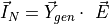
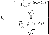
Constant current (I) modelling of three-phase star-connected loads
Traditionally, in positive sequence power flow analysis, constant current loads are directly stored in the  vector. However, since we are performing a three-phase power flow, the voltage angles of phases b and c are not zero,
so they must be taken into account. For both three-phase current star-connected loads, the defined phase currents are
stored in the vector as follows:
vector. However, since we are performing a three-phase power flow, the voltage angles of phases b and c are not zero,
so they must be taken into account. For both three-phase current star-connected loads, the defined phase currents are
stored in the vector as follows:

Example
import VeraGridEngine.api as gce
from VeraGridEngine import ShuntConnectionType

logger = gce.Logger()
grid = gce.MultiCircuit()

# ----------------------------------------------------------------------------------------------------------------------
# Buses
# ----------------------------------------------------------------------------------------------------------------------
bus = gce.Bus(name='Bus', Vnom=0.48)
grid.add_bus(obj=bus)

# ----------------------------------------------------------------------------------------------------------------------
# Three-phase star current load
# ----------------------------------------------------------------------------------------------------------------------
load = gce.Load(Ir1=0.160,
                Ii1=0.110,
                Ir2=0.120,
                Ii2=0.090,
                Ir3=0.120,
                Ii3=0.090)
load.conn = ShuntConnectionType.GroundedStar
grid.add_load(bus=bus, api_obj=load)
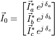
Constant current (I) modelling of three-phase delta-connected loads
However, if the current load is defined in delta connection, the vector shown bellow will be used to mathematically model the element:
Note that for loads connected between phases, the voltage angle to be applied is not that of the phase to which the current load will be mapped, but rather the angle of the voltage difference between the two phases to which the current-defined load is connected. Then, the angles will be updated in each iteration, adding significant complexity compared to the traditional power flow.

Example
import VeraGridEngine.api as gce
from VeraGridEngine import ShuntConnectionType

logger = gce.Logger()
grid = gce.MultiCircuit()

# ----------------------------------------------------------------------------------------------------------------------
# Buses
# ----------------------------------------------------------------------------------------------------------------------
bus = gce.Bus(name='Bus', Vnom=0.48)
grid.add_bus(obj=bus)

# ----------------------------------------------------------------------------------------------------------------------
# Three-phase delta current load
# ----------------------------------------------------------------------------------------------------------------------
load = gce.Load(Ir1=0.160,
                Ii1=0.110,
                Ir2=0.120,
                Ii2=0.090,
                Ir3=0.120,
                Ii3=0.090)
load.conn = ShuntConnectionType.Delta
grid.add_load(bus=bus, api_obj=load)
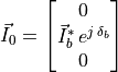
Constant current (I) modelling of two-phase loads
Two-phase current loads, connected for instance between phases  and
and  , are modelled in the same way as three-phase
delta-connected loads. The only difference is that, in this case, the current is defined solely as
, are modelled in the same way as three-phase
delta-connected loads. The only difference is that, in this case, the current is defined solely as  , while the
other phase-to-phase currents remain zero:
, while the
other phase-to-phase currents remain zero:

Example
import VeraGridEngine.api as gce
from VeraGridEngine import ShuntConnectionType

logger = gce.Logger()
grid = gce.MultiCircuit()

# ----------------------------------------------------------------------------------------------------------------------
# Buses
# ----------------------------------------------------------------------------------------------------------------------
bus = gce.Bus(name='Bus', Vnom=0.48)
grid.add_bus(obj=bus)

# ----------------------------------------------------------------------------------------------------------------------
# Two-phase current load
# ----------------------------------------------------------------------------------------------------------------------
load = gce.Load(Ir1=0.0,
                Ii1=0.0,
                Ir2=0.0,
                Ii2=0.0,
                Ir3=0.170,
                Ii3=0.151)
load.conn = ShuntConnectionType.Delta
grid.add_load(bus=bus, api_obj=load)
Constant current (I) modelling of single-phase loads
Finally, single-phase current loads, connected for instance to phase  , are modelled in the same way as three-phase
star-connected loads. The difference lies in the fact that the absent phases are stored with a value of zero.
, are modelled in the same way as three-phase
star-connected loads. The difference lies in the fact that the absent phases are stored with a value of zero.

Example
import VeraGridEngine.api as gce
from VeraGridEngine import ShuntConnectionType

logger = gce.Logger()
grid = gce.MultiCircuit()

# ----------------------------------------------------------------------------------------------------------------------
# Buses
# ----------------------------------------------------------------------------------------------------------------------
bus = gce.Bus(name='Bus', Vnom=0.48)
grid.add_bus(obj=bus)

# ----------------------------------------------------------------------------------------------------------------------
# Single-phase current load
# ----------------------------------------------------------------------------------------------------------------------
load = gce.Load(Ir1=0.0,
                Ii1=0.0,
                Ir2=0.170,
                Ii2=0.080,
                Ir3=0.0,
                Ii3=0.0)
load.conn = ShuntConnectionType.GroundedStar
grid.add_load(bus=bus, api_obj=load)
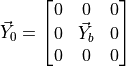
Constant power (P) modelling of three-phase star-connected loads
Finally, we will address the modelling of constant power loads. In the case of a three-phase power load connected in
star, the values defined by the user are stored in the  vector for each phase:


Example
import VeraGridEngine.api as gce
from VeraGridEngine import ShuntConnectionType

logger = gce.Logger()
grid = gce.MultiCircuit()

# ----------------------------------------------------------------------------------------------------------------------
# Buses
# ----------------------------------------------------------------------------------------------------------------------
bus = gce.Bus(name='Bus', Vnom=0.48)
grid.add_bus(obj=bus)

# ----------------------------------------------------------------------------------------------------------------------
# Three-phase star power load
# ----------------------------------------------------------------------------------------------------------------------
load = gce.Load(P1=0.485,
                Q1=0.190,
                P2=0.068,
                Q2=0.060,
                P3=0.290,
                Q3=0.212)
load.conn = ShuntConnectionType.GroundedStar
grid.add_load(bus=bus, api_obj=load)
Constant power (P) modelling of three-phase delta-connected loads
In contrast, if the three-phase power load is connected in delta, the developed transformation to its star equivalent involves the phase-to-ground voltages. Then, the power transformation vector to star will be updated in each iteration, adding significant complexity compared to the traditional power flow.

Example
import VeraGridEngine.api as gce
from VeraGridEngine import ShuntConnectionType

logger = gce.Logger()
grid = gce.MultiCircuit()

# ----------------------------------------------------------------------------------------------------------------------
# Buses
# ----------------------------------------------------------------------------------------------------------------------
bus = gce.Bus(name='Bus', Vnom=0.48)
grid.add_bus(obj=bus)

# ----------------------------------------------------------------------------------------------------------------------
# Three-phase delta power load
# ----------------------------------------------------------------------------------------------------------------------
load = gce.Load(P1=0.385,
                Q1=0.220,
                P2=0.385,
                Q2=0.220,
                P3=0.385,
                Q3=0.220)
load.conn = ShuntConnectionType.Delta
grid.add_load(bus=bus, api_obj=load)
Constant power (P) modelling of two-phase loads
Two-phase power loads, connected for instance between phases and , are modelled in the same way as three-phase
delta-connected loads. The only difference is that, in this case, the power is defined solely as  , while the
other phase-to-phase powers remain zero:
, while the
other phase-to-phase powers remain zero:

Example
import VeraGridEngine.api as gce
from VeraGridEngine import ShuntConnectionType

logger = gce.Logger()
grid = gce.MultiCircuit()

# ----------------------------------------------------------------------------------------------------------------------
# Buses
# ----------------------------------------------------------------------------------------------------------------------
bus = gce.Bus(name='Bus', Vnom=0.48)
grid.add_bus(obj=bus)

# ----------------------------------------------------------------------------------------------------------------------
# Two-phase power load
# ----------------------------------------------------------------------------------------------------------------------
load = gce.Load(P1=0.0,
                Q1=0.0,
                P2=0.0,
                Q2=0.0,
                P3=0.160,
                Q3=0.110)
load.conn = ShuntConnectionType.Delta
grid.add_load(bus=bus, api_obj=load)
Constant power (P) modelling of single-phase loads
Finally, single-phase power loads, connected for instance to phase , are modelled in the same way as three-phase
star-connected loads. The difference lies in the fact that the absent phases are stored with a value of zero:


Example
import VeraGridEngine.api as gce
from VeraGridEngine import ShuntConnectionType

logger = gce.Logger()
grid = gce.MultiCircuit()

# ----------------------------------------------------------------------------------------------------------------------
# Buses
# ----------------------------------------------------------------------------------------------------------------------
bus = gce.Bus(name='Bus', Vnom=0.48)
grid.add_bus(obj=bus)

# ----------------------------------------------------------------------------------------------------------------------
# Single-phase power load
# ----------------------------------------------------------------------------------------------------------------------
load = gce.Load(P1=0.0,
                Q1=0.0,
                P2=0.170,
                Q2=0.125,
                P3=0.0,
                Q3=0.0)
load.conn = ShuntConnectionType.GroundedStar
grid.add_load(bus=bus, api_obj=load)
Registered properties
Profile-enabled properties: active, Cost, shift_key, P, Pa, Pb, Pc, Q, Qa, Qb, Qc, Ir, Ir1, Ir2, Ir3, Ii, Ii1, Ii2, Ii3, G, G1, G2, G3, B, B1, B2, B3, n_customers.
name |
class_type |
unit |
mandatory |
max_chars |
descriptions |
has_profile |
comment |
|---|---|---|---|---|---|---|---|
idtag |
str |
False |
Unique ID |
False |
|||
name |
str |
False |
Name of the device. |
False |
|||
code |
str |
False |
Secondary ID |
False |
|||
rdfid |
str |
False |
RDF ID for further compatibility |
False |
|||
action |
enum ActionType |
False |
Object action to perform. Only used for model merging. |
False |
|||
comment |
str |
False |
User comment |
False |
|||
diff_changes |
MergeInformation |
False |
False |
||||
modelling_authority |
Modelling Authority |
False |
Modelling authority of this asset |
False |
|||
commissioned_date |
int |
False |
Commissioned date of the asset |
False |
|||
decommissioned_date |
int |
False |
Decommissioned date of the asset |
False |
|||
build_status |
enum BuildStatus |
False |
Device build status. Used in expansion planning. |
False |
|||
owners |
AssociationsList |
p.u. |
False |
Owners associations to injections |
False |
||
rms_model |
DaeBlock |
False |
RMS dynamic model |
False |
|||
emt_model |
DaeBlock |
False |
EMT dynamic model |
False |
|||
rms_template |
RMS template |
False |
Native RMS template used. Assigning it clears rms_fmu_template. |
False |
|||
emt_template |
EMT template |
False |
Native EMT template used. Assigning it clears emt_fmu_template. |
False |
|||
rms_fmu_template |
FMU template |
False |
RMS FMU template used only by RMS simulations. Assigning it clears rms_template. |
False |
|||
emt_fmu_template |
FMU template |
False |
EMT FMU template used only by EMT simulations. Assigning it clears emt_template. |
False |
|||
rms_fmu_import_config |
str |
False |
Serialized FMU Co-Simulation RMS configuration |
False |
|||
emt_fmu_import_config |
str |
False |
Serialized FMU Co-Simulation EMT configuration |
False |
|||
rms_fmu_me_import_config |
str |
False |
Serialized FMU Model Exchange RMS configuration |
False |
|||
emt_fmu_me_import_config |
str |
False |
Serialized FMU Model Exchange EMT configuration |
False |
|||
bus |
Bus |
False |
Connection bus |
False |
|||
active |
bool |
False |
Is the load active? |
True |
|||
color |
str |
False |
Color to paint the element in the map diagram |
False |
|||
mttf |
float |
h |
False |
Mean time to failure |
False |
||
mttr |
float |
h |
False |
Mean time to recovery |
False |
||
capex |
float |
e/MW |
False |
Cost of investment. Used in expansion planning. |
False |
||
opex |
float |
e/MWh |
False |
Cost of operation. Used in expansion planning. |
False |
||
Cost |
float |
e/MWh |
False |
Cost of not served energy. Used in OPF. |
True |
||
facility |
Facility |
False |
Facility where this is located |
False |
|||
technologies |
AssociationsList |
p.u. |
False |
Technologies associations to injections |
False |
||
scalable |
bool |
False |
Is the injection scalable? |
False |
|||
shift_key |
float |
False |
Shift key for net transfer capacity |
True |
|||
longitude |
float |
deg |
False |
longitude of the injection. |
False |
||
latitude |
float |
deg |
False |
latitude of the injection. |
False |
||
use_kw |
bool |
False |
Consider the injections in kW and kVAr? |
False |
|||
conn |
enum ShuntConnectionType |
False |
Connection type for 3-phase studies |
False |
|||
bus_pos |
int |
False |
Aid to locate devices on a busbar |
False |
|||
P |
float |
MW |
False |
Active power |
True |
||
Pa |
float |
MW |
False |
Phase A active power |
True |
||
Pb |
float |
MW |
False |
Phase B active power |
True |
||
Pc |
float |
MW |
False |
Phase C active power |
True |
||
Q |
float |
MVAr |
False |
Reactive power |
True |
||
Qa |
float |
MVAr |
False |
Phase A reactive power |
True |
||
Qb |
float |
MVAr |
False |
Phase B reactive power |
True |
||
Qc |
float |
MVAr |
False |
Phase C reactive power |
True |
||
Ir |
float |
MW |
False |
Active power of the current component at V=1.0 p.u. |
True |
||
Ir1 |
float |
MW |
False |
Active power of the phase 1 current component at V=1.0 p.u. |
True |
||
Ir2 |
float |
MW |
False |
Active power of the phase 2 current component at V=1.0 p.u. |
True |
||
Ir3 |
float |
MW |
False |
Active power of the phase 3 current component at V=1.0 p.u. |
True |
||
Ii |
float |
MVAr |
False |
Reactive power of the current component at V=1.0 p.u. |
True |
||
Ii1 |
float |
MVAr |
False |
Reactive power of the phase 1 current component at V=1.0 p.u. |
True |
||
Ii2 |
float |
MVAr |
False |
Reactive power of the phase 2 current component at V=1.0 p.u. |
True |
||
Ii3 |
float |
MVAr |
False |
Reactive power of the phase 3 current component at V=1.0 p.u. |
True |
||
G |
float |
MW |
False |
Active power of the impedance component at V=1.0 p.u. |
True |
||
G1 |
float |
MW |
False |
Active power of the phase 1 impedance component at V=1.0 p.u. |
True |
||
G2 |
float |
MW |
False |
Active power of the phase 2 impedance component at V=1.0 p.u. |
True |
||
G3 |
float |
MW |
False |
Active power of the phase 3 impedance component at V=1.0 p.u. |
True |
||
B |
float |
MVAr |
False |
Reactive power of the impedance component at V=1.0 p.u. |
True |
||
B1 |
float |
MVAr |
False |
Reactive power of the phase 1 impedance component at V=1.0 p.u. |
True |
||
B2 |
float |
MVAr |
False |
Reactive power of the phase 2 impedance component at V=1.0 p.u. |
True |
||
B3 |
float |
MVAr |
False |
Reactive power of the phase 3 impedance component at V=1.0 p.u. |
True |
||
n_customers |
int |
unit |
False |
Number of customers represented by this load |
True |
||
contract_power |
float |
MW |
False |
Nominal contracted power |
False |
Shunt
Shunt elements were documented together with loads in the original modelling chapter. For shunts, the relevant part is the constant-impedance formulation reproduced below.
Constant impedance (Z) modelling of three-phase star-connected loads and shunts
Constant impedance loads and shunts are defined in terms of conductance G [MW] and susceptance B [MVAr].
If these elements have the three-phases active, and they are connected in star, the diagonal of the 3x3 admittance
matrix  is simply filled with the values defined for each phase:

Example
import VeraGridEngine.api as gce
from VeraGridEngine import ShuntConnectionType

logger = gce.Logger()
grid = gce.MultiCircuit()

# ----------------------------------------------------------------------------------------------------------------------
# Buses
# ----------------------------------------------------------------------------------------------------------------------
bus = gce.Bus(name='Bus', Vnom=0.48)
grid.add_bus(obj=bus)

# ----------------------------------------------------------------------------------------------------------------------
# Three-phase star impedance load
# ----------------------------------------------------------------------------------------------------------------------
load = gce.Load(G1=0.160,
                B1=0.110,
                G2=0.120,
                B2=0.090,
                G3=0.120,
                B3=0.090)
load.conn = ShuntConnectionType.GroundedStar
grid.add_load(bus=bus, api_obj=load)
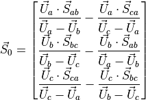
Constant impedance (Z) modelling of three-phase delta-connected loads and shunts
However, if the load is defined in delta connection, the 3x3 matrix shown bellow will be used to mathematically model the load or the shunt element:

Example
import VeraGridEngine.api as gce
from VeraGridEngine import ShuntConnectionType

logger = gce.Logger()
grid = gce.MultiCircuit()

# ----------------------------------------------------------------------------------------------------------------------
# Buses
# ----------------------------------------------------------------------------------------------------------------------
bus = gce.Bus(name='Bus', Vnom=0.48)
grid.add_bus(obj=bus)

# ----------------------------------------------------------------------------------------------------------------------
# Three-phase delta impedance load
# ----------------------------------------------------------------------------------------------------------------------
load = gce.Load(G1=0.160,
                B1=0.110,
                G2=0.120,
                B2=0.090,
                G3=0.120,
                B3=0.090)
load.conn = ShuntConnectionType.Delta
grid.add_load(bus=bus, api_obj=load)
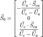
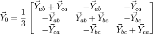
Constant impedance (Z) modelling of two-phase loads and shunts
Two-phase loads and shunts defined as admittances are converted to their corresponding equivalent power values in star
configuration. This conversion is carried out using the voltage, and the resulting power values must be updated at each
iteration of the algorithm. Therefore, in this case, the values are not stored in the admittance matrix but
rather in the power vector  . The current flowing through this type of load is equal to the voltage difference
between the phases to which it is connected, multiplied by its admittance, as shown the equation bellow. By multiplying
the resulting current in each phase by its corresponding voltage, the power value can be obtained.
. The current flowing through this type of load is equal to the voltage difference
between the phases to which it is connected, multiplied by its admittance, as shown the equation bellow. By multiplying
the resulting current in each phase by its corresponding voltage, the power value can be obtained.
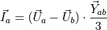
In the case where the load is connected between phases and , the conversion is as follows:
![\vec{S}_0 =
\begin{bmatrix}
\vec{U}_{a} \cdot \left[ (\vec{U}_{a} - \vec{U}_{c}) \cdot \dfrac{\vec{Y}_{ca}}{3} \right]^* \\
0 \\
\vec{U}_{c} \cdot \left[ (\vec{U}_{c} - \vec{U}_{a}) \cdot \dfrac{\vec{Y}_{ca}}{3} \right]^* \\
\end{bmatrix}](../_images/math/95b5540f167309253489dbbc0ec2313c4b09b37f.png)

Example
import VeraGridEngine.api as gce
from VeraGridEngine import ShuntConnectionType

logger = gce.Logger()
grid = gce.MultiCircuit()

# ----------------------------------------------------------------------------------------------------------------------
# Buses
# ----------------------------------------------------------------------------------------------------------------------
bus = gce.Bus(name='Bus', Vnom=0.48)
grid.add_bus(obj=bus)

# ----------------------------------------------------------------------------------------------------------------------
# Two-phase impedance load
# ----------------------------------------------------------------------------------------------------------------------
load = gce.Load(G1=0.0,
                B1=0.0,
                G2=0.0,
                B2=0.0,
                G3=0.230,
                B3=0.132)
load.conn = ShuntConnectionType.Delta
grid.add_load(bus=bus, api_obj=load)
Constant impedance (Z) modelling of single-phase loads and shunts
Finally, single-phase loads and shunt elements are modelled as in the previous three-phase star case, but only saving
the admittance value for the active phase, for instance phase :

Example
import VeraGridEngine.api as gce
from VeraGridEngine import ShuntConnectionType

logger = gce.Logger()
grid = gce.MultiCircuit()

# ----------------------------------------------------------------------------------------------------------------------
# Buses
# ----------------------------------------------------------------------------------------------------------------------
bus = gce.Bus(name='Bus', Vnom=0.48)
grid.add_bus(obj=bus)

# ----------------------------------------------------------------------------------------------------------------------
# Single-phase impedance load
# ----------------------------------------------------------------------------------------------------------------------
load = gce.Load(G1=0.0,
                B1=0.0,
                G2=0.128,
                B2=0.086,
                G3=0.0,
                B3=0.0)
load.conn = ShuntConnectionType.GroundedStar
grid.add_load(bus=bus, api_obj=load)
Registered properties
Profile-enabled properties: active, Cost, shift_key, G, G0, Ga, Gb, Gc, B, B0, Ba, Bb, Bc.
name |
class_type |
unit |
mandatory |
max_chars |
descriptions |
has_profile |
comment |
|---|---|---|---|---|---|---|---|
idtag |
str |
False |
Unique ID |
False |
|||
name |
str |
False |
Name of the device. |
False |
|||
code |
str |
False |
Secondary ID |
False |
|||
rdfid |
str |
False |
RDF ID for further compatibility |
False |
|||
action |
enum ActionType |
False |
Object action to perform. Only used for model merging. |
False |
|||
comment |
str |
False |
User comment |
False |
|||
diff_changes |
MergeInformation |
False |
False |
||||
modelling_authority |
Modelling Authority |
False |
Modelling authority of this asset |
False |
|||
commissioned_date |
int |
False |
Commissioned date of the asset |
False |
|||
decommissioned_date |
int |
False |
Decommissioned date of the asset |
False |
|||
build_status |
enum BuildStatus |
False |
Device build status. Used in expansion planning. |
False |
|||
owners |
AssociationsList |
p.u. |
False |
Owners associations to injections |
False |
||
rms_model |
DaeBlock |
False |
RMS dynamic model |
False |
|||
emt_model |
DaeBlock |
False |
EMT dynamic model |
False |
|||
rms_template |
RMS template |
False |
Native RMS template used. Assigning it clears rms_fmu_template. |
False |
|||
emt_template |
EMT template |
False |
Native EMT template used. Assigning it clears emt_fmu_template. |
False |
|||
rms_fmu_template |
FMU template |
False |
RMS FMU template used only by RMS simulations. Assigning it clears rms_template. |
False |
|||
emt_fmu_template |
FMU template |
False |
EMT FMU template used only by EMT simulations. Assigning it clears emt_template. |
False |
|||
rms_fmu_import_config |
str |
False |
Serialized FMU Co-Simulation RMS configuration |
False |
|||
emt_fmu_import_config |
str |
False |
Serialized FMU Co-Simulation EMT configuration |
False |
|||
rms_fmu_me_import_config |
str |
False |
Serialized FMU Model Exchange RMS configuration |
False |
|||
emt_fmu_me_import_config |
str |
False |
Serialized FMU Model Exchange EMT configuration |
False |
|||
bus |
Bus |
False |
Connection bus |
False |
|||
active |
bool |
False |
Is the load active? |
True |
|||
color |
str |
False |
Color to paint the element in the map diagram |
False |
|||
mttf |
float |
h |
False |
Mean time to failure |
False |
||
mttr |
float |
h |
False |
Mean time to recovery |
False |
||
capex |
float |
e/MW |
False |
Cost of investment. Used in expansion planning. |
False |
||
opex |
float |
e/MWh |
False |
Cost of operation. Used in expansion planning. |
False |
||
Cost |
float |
e/MWh |
False |
Cost of not served energy. Used in OPF. |
True |
||
facility |
Facility |
False |
Facility where this is located |
False |
|||
technologies |
AssociationsList |
p.u. |
False |
Technologies associations to injections |
False |
||
scalable |
bool |
False |
Is the injection scalable? |
False |
|||
shift_key |
float |
False |
Shift key for net transfer capacity |
True |
|||
longitude |
float |
deg |
False |
longitude of the injection. |
False |
||
latitude |
float |
deg |
False |
latitude of the injection. |
False |
||
use_kw |
bool |
False |
Consider the injections in kW and kVAr? |
False |
|||
conn |
enum ShuntConnectionType |
False |
Connection type for 3-phase studies |
False |
|||
bus_pos |
int |
False |
Aid to locate devices on a busbar |
False |
|||
G |
float |
MW |
False |
Active power |
True |
||
G0 |
float |
MW |
False |
Zero sequence active power of the impedance component at V=1.0 p.u. |
True |
||
Ga |
float |
MW |
False |
Active power |
True |
||
Gb |
float |
MW |
False |
Active power |
True |
||
Gc |
float |
MW |
False |
Active power |
True |
||
B |
float |
MVAr |
False |
Reactive power |
True |
||
B0 |
float |
MVAr |
False |
Zero sequence reactive power of the impedance component at V=1.0 p.u. |
True |
||
Ba |
float |
MVAr |
False |
Reactive power |
True |
||
Bb |
float |
MVAr |
False |
Reactive power |
True |
||
Bc |
float |
MVAr |
False |
Reactive power |
True |
||
ysh |
Admittance Matrix |
p.u. |
False |
Shunt admittance matrix of the branch |
False |
ControllableShunt
A ControllableShunt extends shunt modelling with discrete or controllable reactive support behaviour.
This device connects to a bus and contributes power, current, or admittance to the solved network model.
Registered properties
Profile-enabled properties: active, Cost, shift_key, G, G0, Ga, Gb, Gc, B, B0, Ba, Bb, Bc, step, Vset.
name |
class_type |
unit |
mandatory |
max_chars |
descriptions |
has_profile |
comment |
|---|---|---|---|---|---|---|---|
idtag |
str |
False |
Unique ID |
False |
|||
name |
str |
False |
Name of the device. |
False |
|||
code |
str |
False |
Secondary ID |
False |
|||
rdfid |
str |
False |
RDF ID for further compatibility |
False |
|||
action |
enum ActionType |
False |
Object action to perform. Only used for model merging. |
False |
|||
comment |
str |
False |
User comment |
False |
|||
diff_changes |
MergeInformation |
False |
False |
||||
modelling_authority |
Modelling Authority |
False |
Modelling authority of this asset |
False |
|||
commissioned_date |
int |
False |
Commissioned date of the asset |
False |
|||
decommissioned_date |
int |
False |
Decommissioned date of the asset |
False |
|||
build_status |
enum BuildStatus |
False |
Device build status. Used in expansion planning. |
False |
|||
owners |
AssociationsList |
p.u. |
False |
Owners associations to injections |
False |
||
rms_model |
DaeBlock |
False |
RMS dynamic model |
False |
|||
emt_model |
DaeBlock |
False |
EMT dynamic model |
False |
|||
rms_template |
RMS template |
False |
Native RMS template used. Assigning it clears rms_fmu_template. |
False |
|||
emt_template |
EMT template |
False |
Native EMT template used. Assigning it clears emt_fmu_template. |
False |
|||
rms_fmu_template |
FMU template |
False |
RMS FMU template used only by RMS simulations. Assigning it clears rms_template. |
False |
|||
emt_fmu_template |
FMU template |
False |
EMT FMU template used only by EMT simulations. Assigning it clears emt_template. |
False |
|||
rms_fmu_import_config |
str |
False |
Serialized FMU Co-Simulation RMS configuration |
False |
|||
emt_fmu_import_config |
str |
False |
Serialized FMU Co-Simulation EMT configuration |
False |
|||
rms_fmu_me_import_config |
str |
False |
Serialized FMU Model Exchange RMS configuration |
False |
|||
emt_fmu_me_import_config |
str |
False |
Serialized FMU Model Exchange EMT configuration |
False |
|||
bus |
Bus |
False |
Connection bus |
False |
|||
active |
bool |
False |
Is the load active? |
True |
|||
color |
str |
False |
Color to paint the element in the map diagram |
False |
|||
mttf |
float |
h |
False |
Mean time to failure |
False |
||
mttr |
float |
h |
False |
Mean time to recovery |
False |
||
capex |
float |
e/MW |
False |
Cost of investment. Used in expansion planning. |
False |
||
opex |
float |
e/MWh |
False |
Cost of operation. Used in expansion planning. |
False |
||
Cost |
float |
e/MWh |
False |
Cost of not served energy. Used in OPF. |
True |
||
facility |
Facility |
False |
Facility where this is located |
False |
|||
technologies |
AssociationsList |
p.u. |
False |
Technologies associations to injections |
False |
||
scalable |
bool |
False |
Is the injection scalable? |
False |
|||
shift_key |
float |
False |
Shift key for net transfer capacity |
True |
|||
longitude |
float |
deg |
False |
longitude of the injection. |
False |
||
latitude |
float |
deg |
False |
latitude of the injection. |
False |
||
use_kw |
bool |
False |
Consider the injections in kW and kVAr? |
False |
|||
conn |
enum ShuntConnectionType |
False |
Connection type for 3-phase studies |
False |
|||
bus_pos |
int |
False |
Aid to locate devices on a busbar |
False |
|||
G |
float |
MW |
False |
Active power |
True |
||
G0 |
float |
MW |
False |
Zero sequence active power of the impedance component at V=1.0 p.u. |
True |
||
Ga |
float |
MW |
False |
Active power |
True |
||
Gb |
float |
MW |
False |
Active power |
True |
||
Gc |
float |
MW |
False |
Active power |
True |
||
B |
float |
MVAr |
False |
Reactive power |
True |
||
B0 |
float |
MVAr |
False |
Zero sequence reactive power of the impedance component at V=1.0 p.u. |
True |
||
Ba |
float |
MVAr |
False |
Reactive power |
True |
||
Bb |
float |
MVAr |
False |
Reactive power |
True |
||
Bc |
float |
MVAr |
False |
Reactive power |
True |
||
ysh |
Admittance Matrix |
p.u. |
False |
Shunt admittance matrix of the branch |
False |
||
control_mode |
enum ShuntControlMode |
False |
Shunt control mode |
False |
|||
control_bus |
Bus |
False |
Alternative control bus |
False |
|||
g_steps |
Array |
MW@v=1p.u. |
False |
Conductance steps |
False |
||
b_steps |
Array |
MVAr@v=1p.u. |
False |
Susceptance steps |
False |
||
Gmax |
float |
MW |
False |
Maximum conductance |
False |
||
Gmin |
float |
MW |
False |
Minimum conductance |
False |
||
Bmax |
float |
MVAr |
False |
Maximum susceptance |
False |
||
Bmin |
float |
MVAr |
False |
Minimum susceptance |
False |
||
active_steps |
Array |
False |
steps active? |
False |
|||
step |
int |
False |
Device step position (0~N-1) |
True |
|||
Vmin |
float |
p.u. |
False |
Lower range voltage value when regulating with Discrete mode |
False |
||
Vset |
float |
p.u. |
False |
Set voltage. This is used for controlled shunts. |
True |
||
Vmax |
float |
p.u. |
False |
Upper range voltage value when regulating with Discrete mode. |
False |
CurrentInjection
A CurrentInjection injects current directly at a bus and is useful when the source model is expressed naturally in current form.
This device connects to a bus and contributes power, current, or admittance to the solved network model.
Registered properties
Profile-enabled properties: active, Cost, shift_key, Ir, Ir1, Ir2, Ir3, Ii, Ii1, Ii2, Ii3.
name |
class_type |
unit |
mandatory |
max_chars |
descriptions |
has_profile |
comment |
|---|---|---|---|---|---|---|---|
idtag |
str |
False |
Unique ID |
False |
|||
name |
str |
False |
Name of the device. |
False |
|||
code |
str |
False |
Secondary ID |
False |
|||
rdfid |
str |
False |
RDF ID for further compatibility |
False |
|||
action |
enum ActionType |
False |
Object action to perform. Only used for model merging. |
False |
|||
comment |
str |
False |
User comment |
False |
|||
diff_changes |
MergeInformation |
False |
False |
||||
modelling_authority |
Modelling Authority |
False |
Modelling authority of this asset |
False |
|||
commissioned_date |
int |
False |
Commissioned date of the asset |
False |
|||
decommissioned_date |
int |
False |
Decommissioned date of the asset |
False |
|||
build_status |
enum BuildStatus |
False |
Device build status. Used in expansion planning. |
False |
|||
owners |
AssociationsList |
p.u. |
False |
Owners associations to injections |
False |
||
rms_model |
DaeBlock |
False |
RMS dynamic model |
False |
|||
emt_model |
DaeBlock |
False |
EMT dynamic model |
False |
|||
rms_template |
RMS template |
False |
Native RMS template used. Assigning it clears rms_fmu_template. |
False |
|||
emt_template |
EMT template |
False |
Native EMT template used. Assigning it clears emt_fmu_template. |
False |
|||
rms_fmu_template |
FMU template |
False |
RMS FMU template used only by RMS simulations. Assigning it clears rms_template. |
False |
|||
emt_fmu_template |
FMU template |
False |
EMT FMU template used only by EMT simulations. Assigning it clears emt_template. |
False |
|||
rms_fmu_import_config |
str |
False |
Serialized FMU Co-Simulation RMS configuration |
False |
|||
emt_fmu_import_config |
str |
False |
Serialized FMU Co-Simulation EMT configuration |
False |
|||
rms_fmu_me_import_config |
str |
False |
Serialized FMU Model Exchange RMS configuration |
False |
|||
emt_fmu_me_import_config |
str |
False |
Serialized FMU Model Exchange EMT configuration |
False |
|||
bus |
Bus |
False |
Connection bus |
False |
|||
active |
bool |
False |
Is the load active? |
True |
|||
color |
str |
False |
Color to paint the element in the map diagram |
False |
|||
mttf |
float |
h |
False |
Mean time to failure |
False |
||
mttr |
float |
h |
False |
Mean time to recovery |
False |
||
capex |
float |
e/MW |
False |
Cost of investment. Used in expansion planning. |
False |
||
opex |
float |
e/MWh |
False |
Cost of operation. Used in expansion planning. |
False |
||
Cost |
float |
e/MWh |
False |
Cost of not served energy. Used in OPF. |
True |
||
facility |
Facility |
False |
Facility where this is located |
False |
|||
technologies |
AssociationsList |
p.u. |
False |
Technologies associations to injections |
False |
||
scalable |
bool |
False |
Is the injection scalable? |
False |
|||
shift_key |
float |
False |
Shift key for net transfer capacity |
True |
|||
longitude |
float |
deg |
False |
longitude of the injection. |
False |
||
latitude |
float |
deg |
False |
latitude of the injection. |
False |
||
use_kw |
bool |
False |
Consider the injections in kW and kVAr? |
False |
|||
conn |
enum ShuntConnectionType |
False |
Connection type for 3-phase studies |
False |
|||
bus_pos |
int |
False |
Aid to locate devices on a busbar |
False |
|||
Ir |
float |
MW |
False |
Active power of the current component at V=1.0 p.u. |
True |
||
Ir1 |
float |
MW |
False |
Active power of the current component at V=1.0 p.u. |
True |
||
Ir2 |
float |
MW |
False |
Active power of the current component at V=1.0 p.u. |
True |
||
Ir3 |
float |
MW |
False |
Active power of the current component at V=1.0 p.u. |
True |
||
Ii |
float |
MVAr |
False |
Reactive power of the current component at V=1.0 p.u. |
True |
||
Ii1 |
float |
MVAr |
False |
Reactive power of the current component at V=1.0 p.u. |
True |
||
Ii2 |
float |
MVAr |
False |
Reactive power of the current component at V=1.0 p.u. |
True |
||
Ii3 |
float |
MVAr |
False |
Reactive power of the current component at V=1.0 p.u. |
True |
StaticGenerator
A StaticGenerator represents a fixed injection without the full control surface of a synchronous generator.
This device connects to a bus and contributes power, current, or admittance to the solved network model.
Registered properties
Profile-enabled properties: active, Cost, shift_key, P, Pa, Pb, Pc, Q, Qa, Qb, Qc.
name |
class_type |
unit |
mandatory |
max_chars |
descriptions |
has_profile |
comment |
|---|---|---|---|---|---|---|---|
idtag |
str |
False |
Unique ID |
False |
|||
name |
str |
False |
Name of the device. |
False |
|||
code |
str |
False |
Secondary ID |
False |
|||
rdfid |
str |
False |
RDF ID for further compatibility |
False |
|||
action |
enum ActionType |
False |
Object action to perform. Only used for model merging. |
False |
|||
comment |
str |
False |
User comment |
False |
|||
diff_changes |
MergeInformation |
False |
False |
||||
modelling_authority |
Modelling Authority |
False |
Modelling authority of this asset |
False |
|||
commissioned_date |
int |
False |
Commissioned date of the asset |
False |
|||
decommissioned_date |
int |
False |
Decommissioned date of the asset |
False |
|||
build_status |
enum BuildStatus |
False |
Device build status. Used in expansion planning. |
False |
|||
owners |
AssociationsList |
p.u. |
False |
Owners associations to injections |
False |
||
rms_model |
DaeBlock |
False |
RMS dynamic model |
False |
|||
emt_model |
DaeBlock |
False |
EMT dynamic model |
False |
|||
rms_template |
RMS template |
False |
Native RMS template used. Assigning it clears rms_fmu_template. |
False |
|||
emt_template |
EMT template |
False |
Native EMT template used. Assigning it clears emt_fmu_template. |
False |
|||
rms_fmu_template |
FMU template |
False |
RMS FMU template used only by RMS simulations. Assigning it clears rms_template. |
False |
|||
emt_fmu_template |
FMU template |
False |
EMT FMU template used only by EMT simulations. Assigning it clears emt_template. |
False |
|||
rms_fmu_import_config |
str |
False |
Serialized FMU Co-Simulation RMS configuration |
False |
|||
emt_fmu_import_config |
str |
False |
Serialized FMU Co-Simulation EMT configuration |
False |
|||
rms_fmu_me_import_config |
str |
False |
Serialized FMU Model Exchange RMS configuration |
False |
|||
emt_fmu_me_import_config |
str |
False |
Serialized FMU Model Exchange EMT configuration |
False |
|||
bus |
Bus |
False |
Connection bus |
False |
|||
active |
bool |
False |
Is the load active? |
True |
|||
color |
str |
False |
Color to paint the element in the map diagram |
False |
|||
mttf |
float |
h |
False |
Mean time to failure |
False |
||
mttr |
float |
h |
False |
Mean time to recovery |
False |
||
capex |
float |
e/MW |
False |
Cost of investment. Used in expansion planning. |
False |
||
opex |
float |
e/MWh |
False |
Cost of operation. Used in expansion planning. |
False |
||
Cost |
float |
e/MWh |
False |
Cost of not served energy. Used in OPF. |
True |
||
facility |
Facility |
False |
Facility where this is located |
False |
|||
technologies |
AssociationsList |
p.u. |
False |
Technologies associations to injections |
False |
||
scalable |
bool |
False |
Is the injection scalable? |
False |
|||
shift_key |
float |
False |
Shift key for net transfer capacity |
True |
|||
longitude |
float |
deg |
False |
longitude of the injection. |
False |
||
latitude |
float |
deg |
False |
latitude of the injection. |
False |
||
use_kw |
bool |
False |
Consider the injections in kW and kVAr? |
False |
|||
conn |
enum ShuntConnectionType |
False |
Connection type for 3-phase studies |
False |
|||
bus_pos |
int |
False |
Aid to locate devices on a busbar |
False |
|||
P |
float |
MW |
False |
Active power |
True |
||
Pa |
float |
MW |
False |
Phase A active power |
True |
||
Pb |
float |
MW |
False |
Phase B active power |
True |
||
Pc |
float |
MW |
False |
Phase C active power |
True |
||
Q |
float |
MVAr |
False |
Reactive power |
True |
||
Qa |
float |
MVAr |
False |
Phase A reactive power |
True |
||
Qb |
float |
MVAr |
False |
Phase B reactive power |
True |
||
Qc |
float |
MVAr |
False |
Phase C reactive power |
True |
||
Snom |
float |
MVA |
False |
Nominal power. |
False |
ExternalGrid
An ExternalGrid represents an equivalent network connection used to model an upstream or boundary system.
This device connects to a bus and contributes power, current, or admittance to the solved network model.
Registered properties
Profile-enabled properties: active, Cost, shift_key, P, Pa, Pb, Pc, Q, Qa, Qb, Qc, Vm, Va.
name |
class_type |
unit |
mandatory |
max_chars |
descriptions |
has_profile |
comment |
|---|---|---|---|---|---|---|---|
idtag |
str |
False |
Unique ID |
False |
|||
name |
str |
False |
Name of the device. |
False |
|||
code |
str |
False |
Secondary ID |
False |
|||
rdfid |
str |
False |
RDF ID for further compatibility |
False |
|||
action |
enum ActionType |
False |
Object action to perform. Only used for model merging. |
False |
|||
comment |
str |
False |
User comment |
False |
|||
diff_changes |
MergeInformation |
False |
False |
||||
modelling_authority |
Modelling Authority |
False |
Modelling authority of this asset |
False |
|||
commissioned_date |
int |
False |
Commissioned date of the asset |
False |
|||
decommissioned_date |
int |
False |
Decommissioned date of the asset |
False |
|||
build_status |
enum BuildStatus |
False |
Device build status. Used in expansion planning. |
False |
|||
owners |
AssociationsList |
p.u. |
False |
Owners associations to injections |
False |
||
rms_model |
DaeBlock |
False |
RMS dynamic model |
False |
|||
emt_model |
DaeBlock |
False |
EMT dynamic model |
False |
|||
rms_template |
RMS template |
False |
Native RMS template used. Assigning it clears rms_fmu_template. |
False |
|||
emt_template |
EMT template |
False |
Native EMT template used. Assigning it clears emt_fmu_template. |
False |
|||
rms_fmu_template |
FMU template |
False |
RMS FMU template used only by RMS simulations. Assigning it clears rms_template. |
False |
|||
emt_fmu_template |
FMU template |
False |
EMT FMU template used only by EMT simulations. Assigning it clears emt_template. |
False |
|||
rms_fmu_import_config |
str |
False |
Serialized FMU Co-Simulation RMS configuration |
False |
|||
emt_fmu_import_config |
str |
False |
Serialized FMU Co-Simulation EMT configuration |
False |
|||
rms_fmu_me_import_config |
str |
False |
Serialized FMU Model Exchange RMS configuration |
False |
|||
emt_fmu_me_import_config |
str |
False |
Serialized FMU Model Exchange EMT configuration |
False |
|||
bus |
Bus |
False |
Connection bus |
False |
|||
active |
bool |
False |
Is the load active? |
True |
|||
color |
str |
False |
Color to paint the element in the map diagram |
False |
|||
mttf |
float |
h |
False |
Mean time to failure |
False |
||
mttr |
float |
h |
False |
Mean time to recovery |
False |
||
capex |
float |
e/MW |
False |
Cost of investment. Used in expansion planning. |
False |
||
opex |
float |
e/MWh |
False |
Cost of operation. Used in expansion planning. |
False |
||
Cost |
float |
e/MWh |
False |
Cost of not served energy. Used in OPF. |
True |
||
facility |
Facility |
False |
Facility where this is located |
False |
|||
technologies |
AssociationsList |
p.u. |
False |
Technologies associations to injections |
False |
||
scalable |
bool |
False |
Is the injection scalable? |
False |
|||
shift_key |
float |
False |
Shift key for net transfer capacity |
True |
|||
longitude |
float |
deg |
False |
longitude of the injection. |
False |
||
latitude |
float |
deg |
False |
latitude of the injection. |
False |
||
use_kw |
bool |
False |
Consider the injections in kW and kVAr? |
False |
|||
conn |
enum ShuntConnectionType |
False |
Connection type for 3-phase studies |
False |
|||
bus_pos |
int |
False |
Aid to locate devices on a busbar |
False |
|||
P |
float |
MW |
False |
Active power |
True |
||
Pa |
float |
MW |
False |
Phase A active power |
True |
||
Pb |
float |
MW |
False |
Phase B active power |
True |
||
Pc |
float |
MW |
False |
Phase C active power |
True |
||
Q |
float |
MVAr |
False |
Reactive power |
True |
||
Qa |
float |
MVAr |
False |
Phase A reactive power |
True |
||
Qb |
float |
MVAr |
False |
Phase B reactive power |
True |
||
Qc |
float |
MVAr |
False |
Phase C reactive power |
True |
||
mode |
enum ExternalGridMode |
False |
Operation mode of the external grid (voltage or load) |
False |
|||
substituted_device_id |
str |
False |
idtag of the device that was substituted by this external grid equivalent |
False |
|||
Vm |
float |
p.u. |
False |
Active power |
True |
||
Va |
float |
radians |
False |
Reactive power |
True |
Line
Power lines are essential in delivering electricity from generation to loads. They consist of phase conductors
positioned above the ground, sometimes using it as a return path, which must be considered in parameter calculations.
Transmission lines may use bundled conductors and ground wires, while distribution lines can include a neutral return.
Both types can introduce geometric and electrical unbalances. Accurate modelling aims to calculate voltage drops and
losses, based on determining the per-unit-length parameters: resistance  , inductance
  , conductance
  ,
and capacitance
,
and capacitance  .
.

π model
Transmission lines are mathematically modelled to describe their electrical behaviour. The inductive and resistive
effects of multiconductor lines are represented by a series impedance matrix, while capacitive effects are modelled as
a shunt admittance matrix. Together, these form the basis of the  -equivalent model commonly used in power system
studies.
-equivalent model commonly used in power system
studies.

It consists of:
Series impedance:

Shunt admittance:
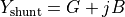
In the -model, represents conductor resistance,  the self and mutual inductive reactances, the shunt
conductance through insulation, and
the self and mutual inductive reactances, the shunt
conductance through insulation, and  the shunt susceptance from line capacitance. Shunt admittance is divided between
the ends, with series impedance in the middle. While the single-phase model is common, unbalanced systems require a 5-wire
representation, the three-phase conductors (, , ), the neutral (
the shunt susceptance from line capacitance. Shunt admittance is divided between
the ends, with series impedance in the middle. While the single-phase model is common, unbalanced systems require a 5-wire
representation, the three-phase conductors (, , ), the neutral ( ), and the ground (
 ). The neutral returns
unbalanced current and stabilises voltage, while the ground provides a fault current path for safety. Each conductor
has its own impedance, and mutual coupling between all conductors requires a
). The neutral returns
unbalanced current and stabilises voltage, while the ground provides a fault current path for safety. Each conductor
has its own impedance, and mutual coupling between all conductors requires a  impedance or admittance matrix.
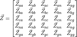
In most transmission lines, the neutral conductor is absent as it is earthed at both ends. The ground return effect can
be incorporated into the phase impedance, allowing the line to be represented with a simplified  matrix.

Series Impedance
Carson’s equations calculate the series self and mutual impedances of overhead transmission lines, accounting for the ground return path. They assume long, horizontally arranged conductors with average height for sag effects, homogeneous and lossless free space, uniform earth properties, and conductor spacing much greater than conductor radius to neglect proximity effects. The impedance matrix elements are derived from the tower geometry and conductor characteristics.

Then, the following equations are implemented to obtain the self and mutual values:
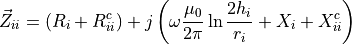
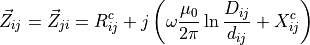
Where:
 and
and  are the internal resistance and reactance of conductor
  in
in  /km.
/km. and
and  are the Carson’s correction terms for earth return effects in /km.
 is the permeability of free space in H/km.
 is the angular frequency in rad/s.
 is the average height above ground of conductor in m.
 is the radius of conductor in m.
 is the distance between conductors and
  in m.
in m. is the distance between conductor and the image of conductor in m.
The correction terms and are derived from an infinite integral representing the impedance contribution due
to the earth return path.
Shunt Admittance
Just as series impedance accounts for resistance and inductance, shunt admittance includes capacitance between conductors and ground, and between conductors themselves. Under the assumptions of lossless air, uniformly grounded earth, and conductor radii much smaller than inter-conductor spacing, these capacitances can be modelled mathematically to compute the corresponding shunt admittances.
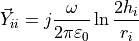
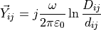
Where  F/m is the free space permittivity.
Kron’s reduction
Kron’s reduction, or node elimination, is a technique from network theory used to simplify a multi-node electrical network by eliminating certain nodes, often called internal or passive nodes, while preserving the electrical behaviour at the remaining nodes.
Assuming a set of nodes divided into two groups between ground conductors (to eliminate) and phase conductors  (to keep), the impedance matrix is partitioned accordingly:
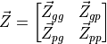
Where:
 is the impedance between eliminated nodes.
 is the mutual impedance between eliminated and preserved nodes.
 is the mutual impedance between preserved and eliminated nodes.
 is the impedance between preserved nodes.
Then, the network equations are:
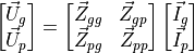
Assuming that the eliminated nodes are held at zero voltage because they are grounded,  . From the
first row of the system:
. From the
first row of the system:
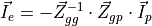
Then, substituting  in the second row:
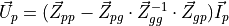
Finally, the Kron-reduced impedance matrix is defined as:
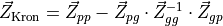
This new matrix allows to describe the electrical behaviour of the remaining phase nodes , while implicitly
incorporating the effect of the eliminated ground nodes , which were assumed to be held at 0 V.
Line definition example
import VeraGridEngine.api as gce
import numpy as np

logger = gce.Logger()
grid = gce.MultiCircuit()
grid.fBase = 60

# ----------------------------------------------------------------------------------------------------------------------
# Buses
# ----------------------------------------------------------------------------------------------------------------------
bus_632 = gce.Bus(name='632', Vnom=4.16, xpos=0, ypos=0)
bus_632.is_slack = True
grid.add_bus(obj=bus_632)

bus_671 = gce.Bus(name='671', Vnom=4.16, xpos=0, ypos=100 * 5)
grid.add_bus(obj=bus_671)

# ----------------------------------------------------------------------------------------------------------------------
# Impedance [Ohm/km] and Admittance [S/km]
# ----------------------------------------------------------------------------------------------------------------------
z_601 = np.array([
    [0.3465 + 1j * 1.0179, 0.1560 + 1j * 0.5017, 0.1580 + 1j * 0.4236],
    [0.1560 + 1j * 0.5017, 0.3375 + 1j * 1.0478, 0.1535 + 1j * 0.3849],
    [0.1580 + 1j * 0.4236, 0.1535 + 1j * 0.3849, 0.3414 + 1j * 1.0348]
], dtype=complex) / 1.60934

y_601 = np.array([
    [1j * 6.2998, 1j * -1.9958, 1j * -1.2595],
    [1j * -1.9958, 1j * 5.9597, 1j * -0.7417],
    [1j * -1.2595, 1j * -0.7417, 1j * 5.6386]
], dtype=complex) / 10 ** 6 / 1.60934

# ----------------------------------------------------------------------------------------------------------------------
# Line Configuration
# ----------------------------------------------------------------------------------------------------------------------
config_601 = gce.create_known_abc_overhead_template(name='Config. 601',
                                                    z_abc=z_601,
                                                    ysh_abc=y_601,
                                                    phases=np.array([1, 2, 3]),
                                                    Vnom=4.16,
                                                    frequency=60)
grid.add_overhead_line(config_601)

# ----------------------------------------------------------------------------------------------------------------------
# Lines Definition
# ----------------------------------------------------------------------------------------------------------------------
line_632_671 = gce.Line(bus_from=bus_632,
                        bus_to=bus_671,
                        length=2000 * 0.0003048)
line_632_671.apply_template(config_601, grid.Sbase, grid.fBase, logger)
grid.add_line(obj=line_632_671)
Definition of a line from the wire configuration
Definition of the exercise
In this tutorial we are going to define a 3-phase line with 4 wires of two different types.
The cable types are the following:
name |
r |
x |
gmr |
max_current |
|---|---|---|---|---|
ACSR 6/1 |
1.050117 |
0.0 |
0.001274 |
180.0 |
Class A / AA |
0.379658 |
0.0 |
0.004267 |
263.0 |
These are taken from the data_sheets__ section
The layout is the following:
Wire |
x(m) |
y(m) |
Phase |
|---|---|---|---|
ACSR 6/1 |
0 |
7 |
1 (A) |
ACSR 6/1 |
0.4 |
7 |
2 (B) |
ACSR 6/1 |
0.8 |
7 |
3 © |
Class A / AA |
0.3 |
6.5 |
0 (N) |
Practice
We may start with a prepared example from the ones provided in the grids and profiles folder.
The example file is Some distribution grid.xlsx. First define the wires that you are going
to use in the tower. For that, we proceed to the tab Database -> Catalogue -> Wire.
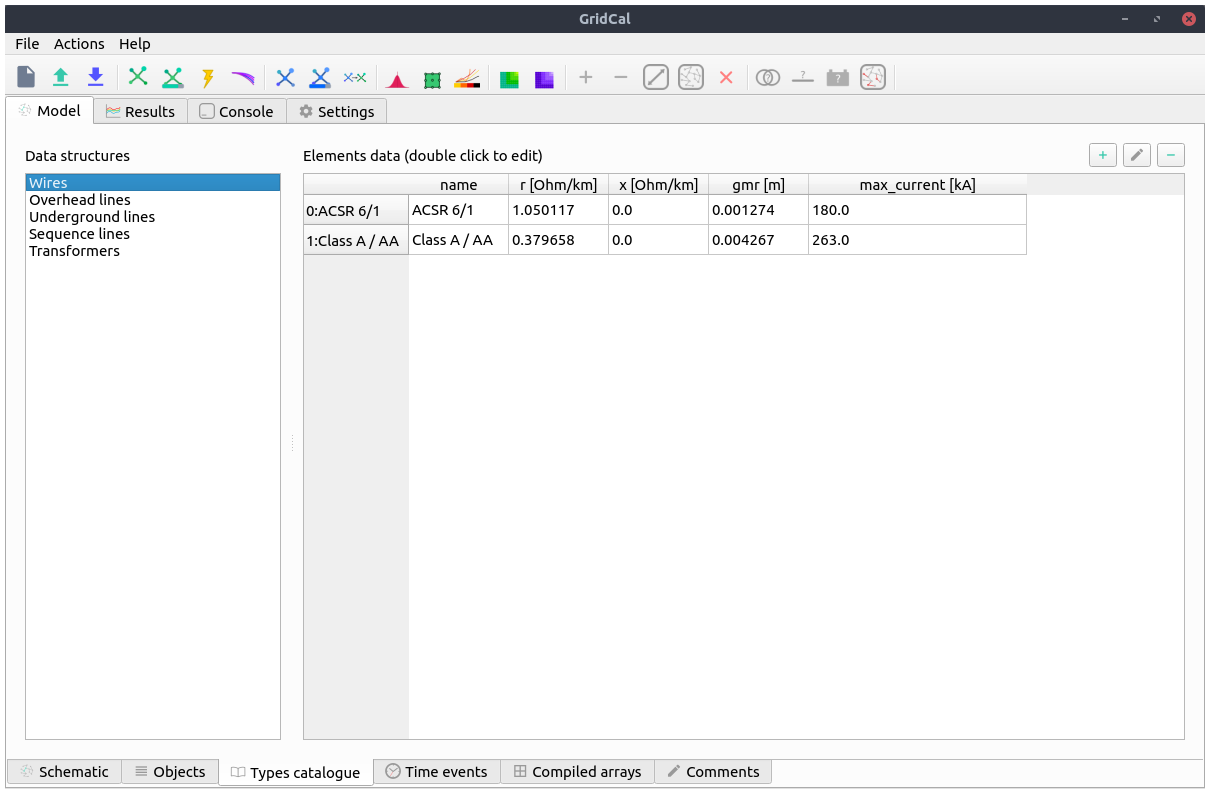
Then, we proceed to the tab Database -> Catalogue -> Tower. Then we select
one of the existing towers or we create one with the (+) button.
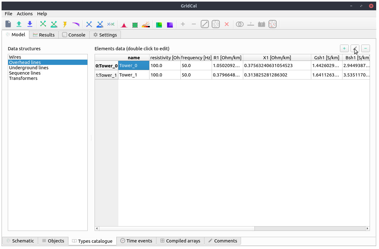
By clicking on the edit button (pencil) we open a new window with the Tower builder editor.
Here we enter the tower definition, and once we are done, we click on the compute button (calculator).
Then the tower cross-section will
be displayed and the results will appear in the following tabs.
This tab shows the series impedance matrix ( ) in several forms:
Per phase without reduction.
Per phase with the neutral embedded.
Sequence reduction.
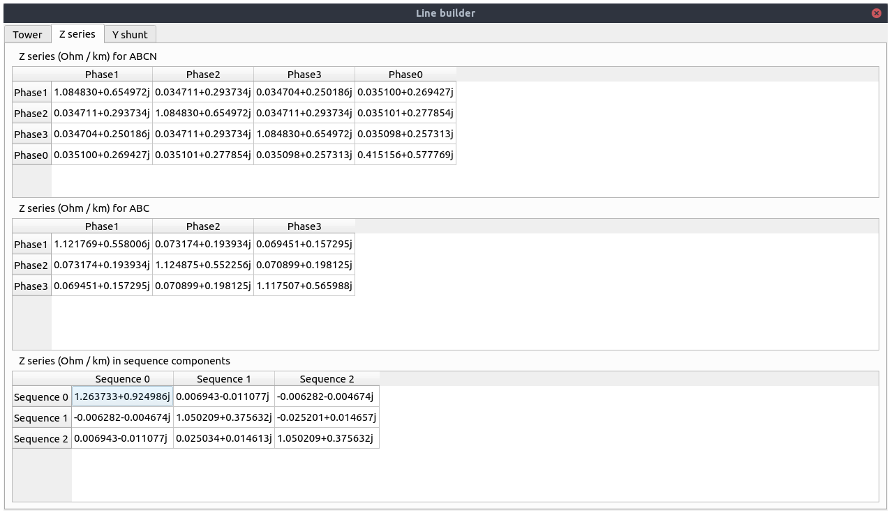
This tab shows the series shunt admittance matrix ( ) in several forms:
Per phase without reduction.
Per phase with the neutral embedded.
Sequence reduction.
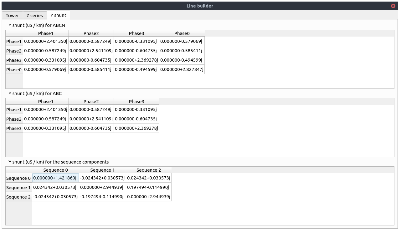
When closed, the values are applied to the overhead line catalogue type that we were editing.
Registered properties
Profile-enabled properties: active, rate, contingency_factor, protection_rating_factor, Cost, temp_oper.
name |
class_type |
unit |
mandatory |
max_chars |
descriptions |
has_profile |
comment |
|---|---|---|---|---|---|---|---|
idtag |
str |
False |
Unique ID |
False |
|||
name |
str |
False |
Name of the device. |
False |
|||
code |
str |
False |
Secondary ID |
False |
|||
rdfid |
str |
False |
RDF ID for further compatibility |
False |
|||
action |
enum ActionType |
False |
Object action to perform. Only used for model merging. |
False |
|||
comment |
str |
False |
User comment |
False |
|||
diff_changes |
MergeInformation |
False |
False |
||||
modelling_authority |
Modelling Authority |
False |
Modelling authority of this asset |
False |
|||
commissioned_date |
int |
False |
Commissioned date of the asset |
False |
|||
decommissioned_date |
int |
False |
Decommissioned date of the asset |
False |
|||
build_status |
enum BuildStatus |
False |
Device build status. Used in expansion planning. |
False |
|||
owners |
AssociationsList |
p.u. |
False |
Owners associations to injections |
False |
||
rms_model |
DaeBlock |
False |
RMS dynamic model |
False |
|||
emt_model |
DaeBlock |
False |
EMT dynamic model |
False |
|||
rms_template |
RMS template |
False |
Native RMS template used. Assigning it clears rms_fmu_template. |
False |
|||
emt_template |
EMT template |
False |
Native EMT template used. Assigning it clears emt_fmu_template. |
False |
|||
rms_fmu_template |
FMU template |
False |
RMS FMU template used only by RMS simulations. Assigning it clears rms_template. |
False |
|||
emt_fmu_template |
FMU template |
False |
EMT FMU template used only by EMT simulations. Assigning it clears emt_template. |
False |
|||
rms_fmu_import_config |
str |
False |
Serialized FMU Co-Simulation RMS configuration |
False |
|||
emt_fmu_import_config |
str |
False |
Serialized FMU Co-Simulation EMT configuration |
False |
|||
rms_fmu_me_import_config |
str |
False |
Serialized FMU Model Exchange RMS configuration |
False |
|||
emt_fmu_me_import_config |
str |
False |
Serialized FMU Model Exchange EMT configuration |
False |
|||
bus_from |
Bus |
False |
Name of the bus at the “from” side |
False |
|||
bus_to |
Bus |
False |
Name of the bus at the “to” side |
False |
|||
active |
bool |
False |
Is active? |
True |
|||
reducible |
bool |
False |
Is the branch to be reduced by the topology preprocessor? |
False |
|||
design_rate |
float |
MVA |
False |
Design thermal rating power that is not modified for operational reasons or otherwise |
False |
||
rate |
float |
MVA |
False |
Operational thermal rating power |
True |
||
contingency_factor |
float |
p.u. |
False |
Rating multiplier for contingencies |
True |
||
protection_rating_factor |
float |
p.u. |
False |
Rating multiplier that indicates the maximum flow before the protections tripping |
True |
||
monitor_loading |
bool |
False |
Monitor this device loading for OPF, NTC or contingency studies. |
False |
|||
mttf |
float |
h |
False |
Mean time to failure |
False |
||
mttr |
float |
h |
False |
Mean time to repair |
False |
||
Cost |
float |
e/MWh |
False |
Cost of overloads. Used in OPF |
True |
||
capex |
float |
e/MW |
False |
Cost of investment. Used in expansion planning. |
False |
||
opex |
float |
e/MWh |
False |
Cost of operation. Used in expansion planning. |
False |
||
group |
Branch group |
False |
Group where this branch belongs |
False |
|||
color |
str |
False |
Color to paint the element in the map diagram |
False |
|||
bus_from_pos |
int |
False |
Aid to locate devices on a busbar |
False |
|||
bus_to_pos |
int |
False |
Aid to locate devices on a busbar |
False |
|||
temp_base |
float |
ºC |
False |
Base temperature at which R was measured. |
False |
||
temp_oper |
float |
ºC |
False |
Operation temperature to modify R. |
True |
||
alpha |
float |
1/ºC |
False |
Thermal coefficient to modify R,around a reference temperature using a linear approximation.For example:Copper @ 20ºC: 0.004041,Copper @ 75ºC: 0.00323,Annealed copper @ 20ºC: 0.00393,Aluminum @ 20ºC: 0.004308,Aluminum @ 75ºC: 0.00330 |
False |
||
R |
float |
p.u. |
False |
Total positive sequence resistance. |
False |
||
X |
float |
p.u. |
False |
Total positive sequence reactance. |
False |
||
B |
float |
p.u. |
False |
Total positive sequence shunt susceptance. |
False |
||
R0 |
float |
p.u. |
False |
Total zero sequence resistance. |
False |
||
X0 |
float |
p.u. |
False |
Total zero sequence reactance. |
False |
||
B0 |
float |
p.u. |
False |
Total zero sequence shunt susceptance. |
False |
||
R2 |
float |
p.u. |
False |
Total negative sequence resistance. |
False |
||
X2 |
float |
p.u. |
False |
Total negative sequence reactance. |
False |
||
B2 |
float |
p.u. |
False |
Total negative sequence shunt susceptance. |
False |
||
ys |
Admittance Matrix |
p.u. |
False |
Series admittance matrix of the branch |
False |
||
ysh |
Admittance Matrix |
p.u. |
False |
Shunt admittance matrix of the branch |
False |
||
tolerance |
float |
% |
False |
Tolerance expected for the impedance values % is expected for transformers0% for lines. |
False |
||
circuit_idx |
int |
False |
Circuit index, used for multiple circuits sharing towers (starts at zero) |
False |
|||
length |
float |
km |
False |
Length of the line (not used for calculation) |
False |
||
template |
Any line template |
False |
False |
||||
locations |
Line locations |
False |
False |
||||
possible_tower_types |
AssociationsList |
False |
Possible overhead line types (>1 to denote association, cat=[PrpCat.PF]), - to denote no association |
False |
|||
possible_underground_line_types |
AssociationsList |
False |
Possible underground line types (>1 to denote association, cat=[PrpCat.PF]), - to denote no association |
False |
|||
possible_sequence_line_types |
AssociationsList |
False |
Possible sequence line types (>1 to denote association, cat=[PrpCat.PF]), - to denote no association |
False |
DcLine
A DcLine models a physical line inside a detailed DC grid, unlike the aggregated HvdcLine transfer model.
This device links terminals or represents a network element between buses.
Registered properties
Profile-enabled properties: active, rate, contingency_factor, protection_rating_factor, Cost, temp_oper.
name |
class_type |
unit |
mandatory |
max_chars |
descriptions |
has_profile |
comment |
|---|---|---|---|---|---|---|---|
idtag |
str |
False |
Unique ID |
False |
|||
name |
str |
False |
Name of the device. |
False |
|||
code |
str |
False |
Secondary ID |
False |
|||
rdfid |
str |
False |
RDF ID for further compatibility |
False |
|||
action |
enum ActionType |
False |
Object action to perform. Only used for model merging. |
False |
|||
comment |
str |
False |
User comment |
False |
|||
diff_changes |
MergeInformation |
False |
False |
||||
modelling_authority |
Modelling Authority |
False |
Modelling authority of this asset |
False |
|||
commissioned_date |
int |
False |
Commissioned date of the asset |
False |
|||
decommissioned_date |
int |
False |
Decommissioned date of the asset |
False |
|||
build_status |
enum BuildStatus |
False |
Device build status. Used in expansion planning. |
False |
|||
owners |
AssociationsList |
p.u. |
False |
Owners associations to injections |
False |
||
rms_model |
DaeBlock |
False |
RMS dynamic model |
False |
|||
emt_model |
DaeBlock |
False |
EMT dynamic model |
False |
|||
rms_template |
RMS template |
False |
Native RMS template used. Assigning it clears rms_fmu_template. |
False |
|||
emt_template |
EMT template |
False |
Native EMT template used. Assigning it clears emt_fmu_template. |
False |
|||
rms_fmu_template |
FMU template |
False |
RMS FMU template used only by RMS simulations. Assigning it clears rms_template. |
False |
|||
emt_fmu_template |
FMU template |
False |
EMT FMU template used only by EMT simulations. Assigning it clears emt_template. |
False |
|||
rms_fmu_import_config |
str |
False |
Serialized FMU Co-Simulation RMS configuration |
False |
|||
emt_fmu_import_config |
str |
False |
Serialized FMU Co-Simulation EMT configuration |
False |
|||
rms_fmu_me_import_config |
str |
False |
Serialized FMU Model Exchange RMS configuration |
False |
|||
emt_fmu_me_import_config |
str |
False |
Serialized FMU Model Exchange EMT configuration |
False |
|||
bus_from |
Bus |
False |
Name of the bus at the “from” side |
False |
|||
bus_to |
Bus |
False |
Name of the bus at the “to” side |
False |
|||
active |
bool |
False |
Is active? |
True |
|||
reducible |
bool |
False |
Is the branch to be reduced by the topology preprocessor? |
False |
|||
design_rate |
float |
MVA |
False |
Design thermal rating power that is not modified for operational reasons or otherwise |
False |
||
rate |
float |
MVA |
False |
Operational thermal rating power |
True |
||
contingency_factor |
float |
p.u. |
False |
Rating multiplier for contingencies |
True |
||
protection_rating_factor |
float |
p.u. |
False |
Rating multiplier that indicates the maximum flow before the protections tripping |
True |
||
monitor_loading |
bool |
False |
Monitor this device loading for OPF, NTC or contingency studies. |
False |
|||
mttf |
float |
h |
False |
Mean time to failure |
False |
||
mttr |
float |
h |
False |
Mean time to repair |
False |
||
Cost |
float |
e/MWh |
False |
Cost of overloads. Used in OPF |
True |
||
capex |
float |
e/MW |
False |
Cost of investment. Used in expansion planning. |
False |
||
opex |
float |
e/MWh |
False |
Cost of operation. Used in expansion planning. |
False |
||
group |
Branch group |
False |
Group where this branch belongs |
False |
|||
color |
str |
False |
Color to paint the element in the map diagram |
False |
|||
bus_from_pos |
int |
False |
Aid to locate devices on a busbar |
False |
|||
bus_to_pos |
int |
False |
Aid to locate devices on a busbar |
False |
|||
temp_base |
float |
ºC |
False |
Base temperature at which R was measured. |
False |
||
temp_oper |
float |
ºC |
False |
Operation temperature to modify R. |
True |
||
alpha |
float |
1/ºC |
False |
Thermal coefficient to modify R,around a reference temperature using a linear approximation.For example:Copper @ 20ºC: 0.004041,Copper @ 75ºC: 0.00323,Annealed copper @ 20ºC: 0.00393,Aluminum @ 20ºC: 0.004308,Aluminum @ 75ºC: 0.00330 |
False |
||
R |
float |
p.u. |
False |
Total positive sequence resistance. |
False |
||
length |
float |
km |
False |
Length of the line (not used for calculation) |
False |
||
r_fault |
float |
p.u. |
False |
Resistance of the mid-line fault.Used in short circuit studies. |
False |
||
fault_pos |
float |
p.u. |
False |
Per-unit positioning of the fault:0 would be at the “from” side,1 would be at the “to” side,therefore 0.5 is at the middle. |
False |
||
template |
Any line template |
False |
False |
||||
locations |
Line locations |
False |
False |
Winding
A Winding is one terminal element of a multi-winding transformer representation and is primarily used inside transformer assemblies.
This device links terminals or represents a network element between buses.
Registered properties
Profile-enabled properties: active, rate, contingency_factor, protection_rating_factor, Cost, temp_oper, tap_module, tap_module_control_mode, vset, Qset, tap_phase, tap_phase_control_mode, Pset.
name |
class_type |
unit |
mandatory |
max_chars |
descriptions |
has_profile |
comment |
|---|---|---|---|---|---|---|---|
idtag |
str |
False |
Unique ID |
False |
|||
name |
str |
False |
Name of the device. |
False |
|||
code |
str |
False |
Secondary ID |
False |
|||
rdfid |
str |
False |
RDF ID for further compatibility |
False |
|||
action |
enum ActionType |
False |
Object action to perform. Only used for model merging. |
False |
|||
comment |
str |
False |
User comment |
False |
|||
diff_changes |
MergeInformation |
False |
False |
||||
modelling_authority |
Modelling Authority |
False |
Modelling authority of this asset |
False |
|||
commissioned_date |
int |
False |
Commissioned date of the asset |
False |
|||
decommissioned_date |
int |
False |
Decommissioned date of the asset |
False |
|||
build_status |
enum BuildStatus |
False |
Device build status. Used in expansion planning. |
False |
|||
owners |
AssociationsList |
p.u. |
False |
Owners associations to injections |
False |
||
rms_model |
DaeBlock |
False |
RMS dynamic model |
False |
|||
emt_model |
DaeBlock |
False |
EMT dynamic model |
False |
|||
rms_template |
RMS template |
False |
Native RMS template used. Assigning it clears rms_fmu_template. |
False |
|||
emt_template |
EMT template |
False |
Native EMT template used. Assigning it clears emt_fmu_template. |
False |
|||
rms_fmu_template |
FMU template |
False |
RMS FMU template used only by RMS simulations. Assigning it clears rms_template. |
False |
|||
emt_fmu_template |
FMU template |
False |
EMT FMU template used only by EMT simulations. Assigning it clears emt_template. |
False |
|||
rms_fmu_import_config |
str |
False |
Serialized FMU Co-Simulation RMS configuration |
False |
|||
emt_fmu_import_config |
str |
False |
Serialized FMU Co-Simulation EMT configuration |
False |
|||
rms_fmu_me_import_config |
str |
False |
Serialized FMU Model Exchange RMS configuration |
False |
|||
emt_fmu_me_import_config |
str |
False |
Serialized FMU Model Exchange EMT configuration |
False |
|||
bus_from |
Bus |
False |
Name of the bus at the “from” side |
False |
|||
bus_to |
Bus |
False |
Name of the bus at the “to” side |
False |
|||
active |
bool |
False |
Is active? |
True |
|||
reducible |
bool |
False |
Is the branch to be reduced by the topology preprocessor? |
False |
|||
design_rate |
float |
MVA |
False |
Design thermal rating power that is not modified for operational reasons or otherwise |
False |
||
rate |
float |
MVA |
False |
Operational thermal rating power |
True |
||
contingency_factor |
float |
p.u. |
False |
Rating multiplier for contingencies |
True |
||
protection_rating_factor |
float |
p.u. |
False |
Rating multiplier that indicates the maximum flow before the protections tripping |
True |
||
monitor_loading |
bool |
False |
Monitor this device loading for OPF, NTC or contingency studies. |
False |
|||
mttf |
float |
h |
False |
Mean time to failure |
False |
||
mttr |
float |
h |
False |
Mean time to repair |
False |
||
Cost |
float |
e/MWh |
False |
Cost of overloads. Used in OPF |
True |
||
capex |
float |
e/MW |
False |
Cost of investment. Used in expansion planning. |
False |
||
opex |
float |
e/MWh |
False |
Cost of operation. Used in expansion planning. |
False |
||
group |
Branch group |
False |
Group where this branch belongs |
False |
|||
color |
str |
False |
Color to paint the element in the map diagram |
False |
|||
bus_from_pos |
int |
False |
Aid to locate devices on a busbar |
False |
|||
bus_to_pos |
int |
False |
Aid to locate devices on a busbar |
False |
|||
temp_base |
float |
ºC |
False |
Base temperature at which R was measured. |
False |
||
temp_oper |
float |
ºC |
False |
Operation temperature to modify R. |
True |
||
alpha |
float |
1/ºC |
False |
Thermal coefficient to modify R,around a reference temperature using a linear approximation.For example:Copper @ 20ºC: 0.004041,Copper @ 75ºC: 0.00323,Annealed copper @ 20ºC: 0.00393,Aluminum @ 20ºC: 0.004308,Aluminum @ 75ºC: 0.00330 |
False |
||
R |
float |
p.u. |
False |
Total positive sequence resistance. |
False |
||
X |
float |
p.u. |
False |
Total positive sequence reactance. |
False |
||
G |
float |
p.u. |
False |
Total positive sequence shunt conductance. |
False |
||
B |
float |
p.u. |
False |
Total positive sequence shunt susceptance. |
False |
||
R0 |
float |
p.u. |
False |
Total zero sequence resistance. |
False |
||
X0 |
float |
p.u. |
False |
Total zero sequence reactance. |
False |
||
G0 |
float |
p.u. |
False |
Total zero sequence shunt conductance. |
False |
||
B0 |
float |
p.u. |
False |
Total zero sequence shunt susceptance. |
False |
||
R2 |
float |
p.u. |
False |
Total negative sequence resistance. |
False |
||
X2 |
float |
p.u. |
False |
Total negative sequence reactance. |
False |
||
G2 |
float |
p.u. |
False |
Total negative sequence shunt conductance. |
False |
||
B2 |
float |
p.u. |
False |
Total negative sequence shunt susceptance. |
False |
||
tolerance |
float |
% |
False |
Tolerance expected for the impedance values% is expected for transformers0% for lines. |
False |
||
tap_changer |
Tap changer |
False |
Tap changer object |
False |
|||
tap_module |
float |
False |
Tap changer module, it a value close to 1.0 |
True |
|||
tap_module_max |
float |
False |
Tap changer module max value |
False |
|||
tap_module_min |
float |
False |
Tap changer module min value |
False |
|||
tap_module_control_mode |
enum TapModuleControl |
False |
Control available with the tap module |
True |
|||
vset |
float |
p.u. |
False |
Objective voltage at the “to” side of the bus when regulating the tap. |
True |
||
Qset |
float |
MVAr |
False |
Objective power at the selected side. |
True |
||
regulation_bus |
Bus |
False |
Bus where the regulation is applied. |
False |
|||
tap_phase |
float |
rad |
False |
Angle shift of the tap changer. |
True |
||
tap_phase_max |
float |
rad |
False |
Max angle. |
False |
||
tap_phase_min |
float |
rad |
False |
Min angle. |
False |
||
tap_phase_control_mode |
enum TapPhaseControl |
False |
Control available with the tap angle |
True |
|||
Pset |
float |
MW |
False |
Objective power at the selected side. |
True |
||
HV |
float |
kV |
False |
High voltage rating |
False |
||
LV |
float |
kV |
False |
Low voltage rating |
False |
||
Sn |
float |
MVA |
False |
Nominal power |
False |
||
Pcu |
float |
kW |
False |
Copper losses (optional) |
False |
||
Pfe |
float |
kW |
False |
Iron losses (optional) |
False |
||
I0 |
float |
% |
False |
No-load current (optional) |
False |
||
Vsc |
float |
% |
False |
Short-circuit voltage (optional) |
False |
||
conn |
enum WindingsConnection |
False |
Windings connection (from, to):G: grounded starS: ungrounded starD: delta |
False |
|||
conn_f |
enum WindingType |
False |
Winding 3 phase connection at the from side |
False |
|||
conn_t |
enum WindingType |
False |
Winding 3 phase connection at the to side |
False |
|||
vector_group_number |
int |
False |
Vector group number. It indicates the structural phase:phase = vector_group_number · 30º |
False |
|||
template |
Transformer type |
False |
False |
Transformer2W
Power transformers link network sections operating at different voltages, such as generators and transmission systems.
For two-winding, three-phase transformers, the winding impedance  is derived from short-circuit tests, and
the iron-core shunt admittance
is derived from short-circuit tests, and
the iron-core shunt admittance  from open-circuit tests. Modelling begins with the schematic of the basic
two-winding transformer:
from open-circuit tests. Modelling begins with the schematic of the basic
two-winding transformer:

A transformer’s primary and secondary windings, with  and
and  turns respectively, have their voltages and
currents related through short-circuit and open-circuit admittance parameters. These relationships are represented in
the transformer’s electrical equivalent circuit:
turns respectively, have their voltages and
currents related through short-circuit and open-circuit admittance parameters. These relationships are represented in
the transformer’s electrical equivalent circuit:

In the per-unit system, the transformer voltage ratio  becomes
  . Many transformers include tap
changers to regulate voltage by adjusting the ratio to
. Many transformers include tap
changers to regulate voltage by adjusting the ratio to  . In the -model, virtual tap transformers
 and
and  reconcile device and bus nominal voltages. From the single-phase transformer model, the corresponding
primitive admittance matrix is then derived to relate primary and secondary voltages and currents.
reconcile device and bus nominal voltages. From the single-phase transformer model, the corresponding
primitive admittance matrix is then derived to relate primary and secondary voltages and currents.
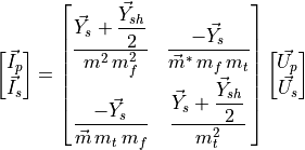
Using nodal analysis, single-phase transformer models can be extended to multi-winding, multi-phase configurations by
mapping winding voltages and currents (e.g., “ ”) into the “
 ” phase frame. The primitive
parameters of three identical single-phase units are then combined to represent the full three-phase transformer.
” phase frame. The primitive
parameters of three identical single-phase units are then combined to represent the full three-phase transformer.
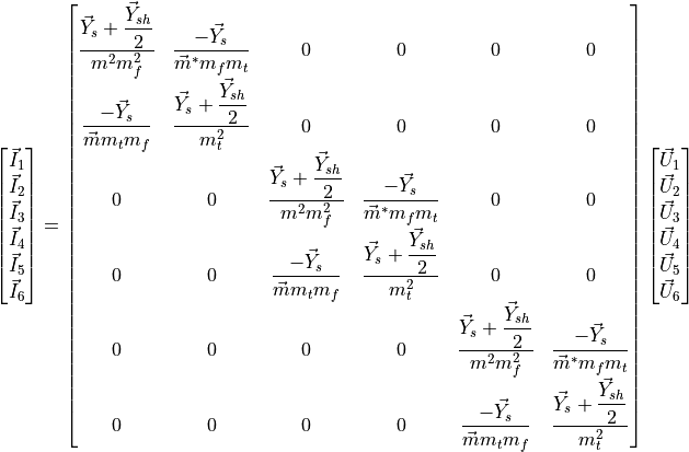
Expressed in compact form, the resulting expression is:
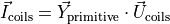
Which can be operated in order to relate phase magnitudes:

It follows that the next step is to find the connectivity matrices  and
and  , which relate the voltages and
currents at each winding to the phase magnitudes, to obtain the transformer admittance matrix
, which relate the voltages and
currents at each winding to the phase magnitudes, to obtain the transformer admittance matrix  .
This matrix links the primary and secondary phase voltages and currents:
.
This matrix links the primary and secondary phase voltages and currents:

The three-phase windings of power transformers may be connected in several ways. In high voltage transmission the most popular connections are star and delta, although the zig-zag connection is also used in distribution systems, depicted in figure bellow. Consequently, connectivity matrices must be computed for each configuration.

For instance, the following figure shows the three-phase delta-star (Dy) connection:

The transformation matrix , which relates the voltages of each winding to the corresponding phase voltages,
is given explicitly in the following expression:
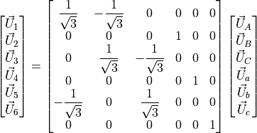
And in compact form:
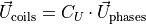
Similarly, the inverse current connectivity matrix  is obtained:
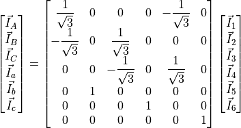
And also in compact form:

The full transformer admittance matrix for the Dy connection is obtained by substituting the connectivity matrices
and :
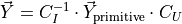
Finally, the transformer admittance matrix for the Dy connection is computed:
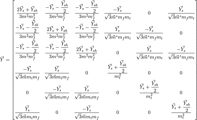
The admittance matrices for the other eight possible configurations have been obtained using exactly the same procedure.
Vector group and clock notation
The vector group and clock notation define the connection type of the high-voltage (HV) and low-voltage (LV) windings of a three-phase transformer, as well as the phase displacement between their voltages. The HV side connection is indicated first using uppercase letters, followed by the LV side in lowercase. The phase displacement is then specified using clock notation:

The full circumference of a clock is  , which, divided by its
  hours, assigns
  to each hour.
If the high-voltage (HV) side is taken as the reference, the low-voltage (LV) side indicates the phase displacement
between the two voltages. For instance, a \textbf{Dy5} transformer connection means that the HV side is delta-connected,
the LV side is star-connected, and the phase displacement between them is
to each hour.
If the high-voltage (HV) side is taken as the reference, the low-voltage (LV) side indicates the phase displacement
between the two voltages. For instance, a \textbf{Dy5} transformer connection means that the HV side is delta-connected,
the LV side is star-connected, and the phase displacement between them is  (
( ), as
illustrated in the figure above.
), as
illustrated in the figure above.
Transformer definition example
import VeraGridEngine.api as gce
from VeraGridEngine import WindingType

logger = gce.Logger()
grid = gce.MultiCircuit()
grid.fBase = 60

# ----------------------------------------------------------------------------------------------------------------------
# Buses
# ----------------------------------------------------------------------------------------------------------------------
bus_1 = gce.Bus(name='633', Vnom=4.16, xpos=100 * 5, ypos=0)
grid.add_bus(obj=bus_1)

bus_2 = gce.Bus(name='634', Vnom=0.48, xpos=200 * 5, ypos=0)
grid.add_bus(obj=bus_2)

# ----------------------------------------------------------------------------------------------------------------------
# Transformer Definition
# ----------------------------------------------------------------------------------------------------------------------
trafo_1 = gce.Transformer2W(name='Transformer',
                            bus_from=bus_1,
                            bus_to=bus_2,
                            HV=4.16,
                            LV=0.48,
                            nominal_power=0.5,
                            rate=0.5,
                            r=1,
                            x=2)
trafo_1.conn_f = WindingType.GroundedStar
trafo_1.conn_t = WindingType.GroundedStar
grid.add_transformer2w(trafo_1)
Transformer definition from SC test values
The transformers are modeled as π branches too. In order to get the series impedance and shunt admittance of the transformer to match the branch model, it is advised to transform the specification sheet values of the device into the desired values. The values to take from the specs sheet are:
 : Nominal power in MVA.
 : Voltage at the high-voltage side in kV.
 : Voltage at the low-voltage side in kV.
 : Nominal voltage of the high-voltage side bus kV.
 : Nominal voltage of the low-voltage side bus kV.
 : Short circuit voltage in %.
 : Copper losses in kW.
 : No load current in %.
 : Contribution to the HV side. Value from 0 to 1.
Short circuit impedance (p.u. of the machine)

Short circuit resistance (p.u. of the machine)
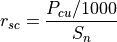
Short circuit reactance (p.u. of the machine)
Can only be computed if 
Series impedance (p.u. of the machine)
The issue with this is that we now must convert  from machine base to the system base.
First we compute the High voltage side:


Now, we compute the Low voltage side:


Finally, the system series impedance in p.u. is:
Now, the leakage impedance (shunt of the model)
Finally, the shunt admittance is (p.u. of the system):
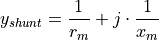
Inverse definition of SC values from π model
In VeraGrid I found the need to find the short circuit values
( ) from the branch values (R, X, G, B). Hence the following formulas:

Registered properties
Profile-enabled properties: active, rate, contingency_factor, protection_rating_factor, Cost, temp_oper, tap_module, tap_module_control_mode, vset, Qset, tap_phase, tap_phase_control_mode, Pset.
name |
class_type |
unit |
mandatory |
max_chars |
descriptions |
has_profile |
comment |
|---|---|---|---|---|---|---|---|
idtag |
str |
False |
Unique ID |
False |
|||
name |
str |
False |
Name of the device. |
False |
|||
code |
str |
False |
Secondary ID |
False |
|||
rdfid |
str |
False |
RDF ID for further compatibility |
False |
|||
action |
enum ActionType |
False |
Object action to perform. Only used for model merging. |
False |
|||
comment |
str |
False |
User comment |
False |
|||
diff_changes |
MergeInformation |
False |
False |
||||
modelling_authority |
Modelling Authority |
False |
Modelling authority of this asset |
False |
|||
commissioned_date |
int |
False |
Commissioned date of the asset |
False |
|||
decommissioned_date |
int |
False |
Decommissioned date of the asset |
False |
|||
build_status |
enum BuildStatus |
False |
Device build status. Used in expansion planning. |
False |
|||
owners |
AssociationsList |
p.u. |
False |
Owners associations to injections |
False |
||
rms_model |
DaeBlock |
False |
RMS dynamic model |
False |
|||
emt_model |
DaeBlock |
False |
EMT dynamic model |
False |
|||
rms_template |
RMS template |
False |
Native RMS template used. Assigning it clears rms_fmu_template. |
False |
|||
emt_template |
EMT template |
False |
Native EMT template used. Assigning it clears emt_fmu_template. |
False |
|||
rms_fmu_template |
FMU template |
False |
RMS FMU template used only by RMS simulations. Assigning it clears rms_template. |
False |
|||
emt_fmu_template |
FMU template |
False |
EMT FMU template used only by EMT simulations. Assigning it clears emt_template. |
False |
|||
rms_fmu_import_config |
str |
False |
Serialized FMU Co-Simulation RMS configuration |
False |
|||
emt_fmu_import_config |
str |
False |
Serialized FMU Co-Simulation EMT configuration |
False |
|||
rms_fmu_me_import_config |
str |
False |
Serialized FMU Model Exchange RMS configuration |
False |
|||
emt_fmu_me_import_config |
str |
False |
Serialized FMU Model Exchange EMT configuration |
False |
|||
bus_from |
Bus |
False |
Name of the bus at the “from” side |
False |
|||
bus_to |
Bus |
False |
Name of the bus at the “to” side |
False |
|||
active |
bool |
False |
Is active? |
True |
|||
reducible |
bool |
False |
Is the branch to be reduced by the topology preprocessor? |
False |
|||
design_rate |
float |
MVA |
False |
Design thermal rating power that is not modified for operational reasons or otherwise |
False |
||
rate |
float |
MVA |
False |
Operational thermal rating power |
True |
||
contingency_factor |
float |
p.u. |
False |
Rating multiplier for contingencies |
True |
||
protection_rating_factor |
float |
p.u. |
False |
Rating multiplier that indicates the maximum flow before the protections tripping |
True |
||
monitor_loading |
bool |
False |
Monitor this device loading for OPF, NTC or contingency studies. |
False |
|||
mttf |
float |
h |
False |
Mean time to failure |
False |
||
mttr |
float |
h |
False |
Mean time to repair |
False |
||
Cost |
float |
e/MWh |
False |
Cost of overloads. Used in OPF |
True |
||
capex |
float |
e/MW |
False |
Cost of investment. Used in expansion planning. |
False |
||
opex |
float |
e/MWh |
False |
Cost of operation. Used in expansion planning. |
False |
||
group |
Branch group |
False |
Group where this branch belongs |
False |
|||
color |
str |
False |
Color to paint the element in the map diagram |
False |
|||
bus_from_pos |
int |
False |
Aid to locate devices on a busbar |
False |
|||
bus_to_pos |
int |
False |
Aid to locate devices on a busbar |
False |
|||
temp_base |
float |
ºC |
False |
Base temperature at which R was measured. |
False |
||
temp_oper |
float |
ºC |
False |
Operation temperature to modify R. |
True |
||
alpha |
float |
1/ºC |
False |
Thermal coefficient to modify R,around a reference temperature using a linear approximation.For example:Copper @ 20ºC: 0.004041,Copper @ 75ºC: 0.00323,Annealed copper @ 20ºC: 0.00393,Aluminum @ 20ºC: 0.004308,Aluminum @ 75ºC: 0.00330 |
False |
||
R |
float |
p.u. |
False |
Total positive sequence resistance. |
False |
||
X |
float |
p.u. |
False |
Total positive sequence reactance. |
False |
||
G |
float |
p.u. |
False |
Total positive sequence shunt conductance. |
False |
||
B |
float |
p.u. |
False |
Total positive sequence shunt susceptance. |
False |
||
R0 |
float |
p.u. |
False |
Total zero sequence resistance. |
False |
||
X0 |
float |
p.u. |
False |
Total zero sequence reactance. |
False |
||
G0 |
float |
p.u. |
False |
Total zero sequence shunt conductance. |
False |
||
B0 |
float |
p.u. |
False |
Total zero sequence shunt susceptance. |
False |
||
R2 |
float |
p.u. |
False |
Total negative sequence resistance. |
False |
||
X2 |
float |
p.u. |
False |
Total negative sequence reactance. |
False |
||
G2 |
float |
p.u. |
False |
Total negative sequence shunt conductance. |
False |
||
B2 |
float |
p.u. |
False |
Total negative sequence shunt susceptance. |
False |
||
tolerance |
float |
% |
False |
Tolerance expected for the impedance values% is expected for transformers0% for lines. |
False |
||
tap_changer |
Tap changer |
False |
Tap changer object |
False |
|||
tap_module |
float |
False |
Tap changer module, it a value close to 1.0 |
True |
|||
tap_module_max |
float |
False |
Tap changer module max value |
False |
|||
tap_module_min |
float |
False |
Tap changer module min value |
False |
|||
tap_module_control_mode |
enum TapModuleControl |
False |
Control available with the tap module |
True |
|||
vset |
float |
p.u. |
False |
Objective voltage at the “to” side of the bus when regulating the tap. |
True |
||
Qset |
float |
MVAr |
False |
Objective power at the selected side. |
True |
||
regulation_bus |
Bus |
False |
Bus where the regulation is applied. |
False |
|||
tap_phase |
float |
rad |
False |
Angle shift of the tap changer. |
True |
||
tap_phase_max |
float |
rad |
False |
Max angle. |
False |
||
tap_phase_min |
float |
rad |
False |
Min angle. |
False |
||
tap_phase_control_mode |
enum TapPhaseControl |
False |
Control available with the tap angle |
True |
|||
Pset |
float |
MW |
False |
Objective power at the selected side. |
True |
||
HV |
float |
kV |
False |
High voltage rating |
False |
||
LV |
float |
kV |
False |
Low voltage rating |
False |
||
Sn |
float |
MVA |
False |
Nominal power |
False |
||
Pcu |
float |
kW |
False |
Copper losses (optional) |
False |
||
Pfe |
float |
kW |
False |
Iron losses (optional) |
False |
||
I0 |
float |
% |
False |
No-load current (optional) |
False |
||
Vsc |
float |
% |
False |
Short-circuit voltage (optional) |
False |
||
conn |
enum WindingsConnection |
False |
Windings connection (from, to):G: grounded starS: ungrounded starD: delta |
False |
|||
conn_f |
enum WindingType |
False |
Winding 3 phase connection at the from side |
False |
|||
conn_t |
enum WindingType |
False |
Winding 3 phase connection at the to side |
False |
|||
vector_group_number |
int |
False |
Vector group number. It indicates the structural phase:phase = vector_group_number · 30º |
False |
|||
template |
Transformer type |
False |
False |
Transformer3W
A Transformer3W stores a three-winding transformer and its associated winding objects.
This device links terminals or represents a network element between buses.
Registered properties
Profile-enabled properties: active.
name |
class_type |
unit |
mandatory |
max_chars |
descriptions |
has_profile |
comment |
|---|---|---|---|---|---|---|---|
idtag |
str |
False |
Unique ID |
False |
|||
name |
str |
False |
Name of the device. |
False |
|||
code |
str |
False |
Secondary ID |
False |
|||
rdfid |
str |
False |
RDF ID for further compatibility |
False |
|||
action |
enum ActionType |
False |
Object action to perform. Only used for model merging. |
False |
|||
comment |
str |
False |
User comment |
False |
|||
diff_changes |
MergeInformation |
False |
False |
||||
modelling_authority |
Modelling Authority |
False |
Modelling authority of this asset |
False |
|||
commissioned_date |
int |
False |
Commissioned date of the asset |
False |
|||
decommissioned_date |
int |
False |
Decommissioned date of the asset |
False |
|||
build_status |
enum BuildStatus |
False |
Device build status. Used in expansion planning. |
False |
|||
owners |
AssociationsList |
p.u. |
False |
Owners associations to injections |
False |
||
bus0 |
Bus |
False |
Middle point connection bus. |
False |
|||
bus1 |
Bus |
False |
Bus 1. |
False |
|||
bus2 |
Bus |
False |
Bus 2. |
False |
|||
bus3 |
Bus |
False |
Bus 3. |
False |
|||
active |
bool |
False |
Is active? |
True |
|||
winding1 |
Winding |
False |
Winding 1. |
False |
|||
winding2 |
Winding |
False |
Winding 2. |
False |
|||
winding3 |
Winding |
False |
Winding 3. |
False |
|||
V1 |
float |
kV |
False |
Side 1 rating |
False |
||
V2 |
float |
kV |
False |
Side 2 rating |
False |
||
V3 |
float |
kV |
False |
Side 3 rating |
False |
||
r12 |
float |
p.u. |
False |
Resistance measured from 1->2 |
False |
||
r23 |
float |
p.u. |
False |
Resistance measured from 2->3 |
False |
||
r31 |
float |
p.u. |
False |
Resistance measured from 3->1 |
False |
||
x12 |
float |
p.u. |
False |
Reactance measured from 1->2 |
False |
||
x23 |
float |
p.u. |
False |
Reactance measured from 2->3 |
False |
||
x31 |
float |
p.u. |
False |
Reactance measured from 3->1 |
False |
||
rate1 |
float |
MVA |
False |
Rating 1 |
False |
||
rate2 |
float |
MVA |
False |
Rating 2 |
False |
||
rate3 |
float |
MVA |
False |
Rating 3 |
False |
||
Pcu12 |
float |
KW |
False |
Copper loss between 1->2 |
False |
||
Pcu23 |
float |
KW |
False |
Copper loss between 2->3 |
False |
||
Pcu31 |
float |
KW |
False |
Copper loss between 3->1 |
False |
||
Vsc12 |
float |
% |
False |
Short-circuit voltage between 1->2 |
False |
||
Vsc23 |
float |
% |
False |
Short-circuit voltage between 2->3 |
False |
||
Vsc31 |
float |
% |
False |
Short-circuit voltage between 3->1 |
False |
||
Pfe |
float |
KW |
False |
Iron loss |
False |
||
I0 |
float |
% |
False |
No-load current |
False |
||
x |
float |
px |
False |
x position |
False |
||
y |
float |
px |
False |
y position |
False |
TransformerNW
A TransformerNW generalizes transformer representation to an arbitrary number of windings.
This device links terminals or represents a network element between buses.
Registered properties
Profile-enabled properties: active.
name |
class_type |
unit |
mandatory |
max_chars |
descriptions |
has_profile |
comment |
|---|---|---|---|---|---|---|---|
idtag |
str |
False |
Unique ID |
False |
|||
name |
str |
False |
Name of the device. |
False |
|||
code |
str |
False |
Secondary ID |
False |
|||
rdfid |
str |
False |
RDF ID for further compatibility |
False |
|||
action |
enum ActionType |
False |
Object action to perform. Only used for model merging. |
False |
|||
comment |
str |
False |
User comment |
False |
|||
diff_changes |
MergeInformation |
False |
False |
||||
modelling_authority |
Modelling Authority |
False |
Modelling authority of this asset |
False |
|||
commissioned_date |
int |
False |
Commissioned date of the asset |
False |
|||
decommissioned_date |
int |
False |
Decommissioned date of the asset |
False |
|||
build_status |
enum BuildStatus |
False |
Device build status. Used in expansion planning. |
False |
|||
owners |
AssociationsList |
p.u. |
False |
Owners associations to injections |
False |
||
bus0 |
Bus |
False |
Middle point connection bus. |
False |
|||
active |
bool |
False |
Is active? |
True |
|||
winding_count |
int |
False |
Number of windings. |
False |
|||
Pfe |
float |
kW |
False |
Iron loss |
False |
||
I0 |
float |
% |
False |
No-load current |
False |
||
x |
float |
px |
False |
x position |
False |
||
y |
float |
px |
False |
y position |
False |
SeriesReactance
A SeriesReactance is a branch whose main purpose is to model concentrated series reactance between buses.
This device links terminals or represents a network element between buses.
Registered properties
Profile-enabled properties: active, rate, contingency_factor, protection_rating_factor, Cost, temp_oper.
name |
class_type |
unit |
mandatory |
max_chars |
descriptions |
has_profile |
comment |
|---|---|---|---|---|---|---|---|
idtag |
str |
False |
Unique ID |
False |
|||
name |
str |
False |
Name of the device. |
False |
|||
code |
str |
False |
Secondary ID |
False |
|||
rdfid |
str |
False |
RDF ID for further compatibility |
False |
|||
action |
enum ActionType |
False |
Object action to perform. Only used for model merging. |
False |
|||
comment |
str |
False |
User comment |
False |
|||
diff_changes |
MergeInformation |
False |
False |
||||
modelling_authority |
Modelling Authority |
False |
Modelling authority of this asset |
False |
|||
commissioned_date |
int |
False |
Commissioned date of the asset |
False |
|||
decommissioned_date |
int |
False |
Decommissioned date of the asset |
False |
|||
build_status |
enum BuildStatus |
False |
Device build status. Used in expansion planning. |
False |
|||
owners |
AssociationsList |
p.u. |
False |
Owners associations to injections |
False |
||
rms_model |
DaeBlock |
False |
RMS dynamic model |
False |
|||
emt_model |
DaeBlock |
False |
EMT dynamic model |
False |
|||
rms_template |
RMS template |
False |
Native RMS template used. Assigning it clears rms_fmu_template. |
False |
|||
emt_template |
EMT template |
False |
Native EMT template used. Assigning it clears emt_fmu_template. |
False |
|||
rms_fmu_template |
FMU template |
False |
RMS FMU template used only by RMS simulations. Assigning it clears rms_template. |
False |
|||
emt_fmu_template |
FMU template |
False |
EMT FMU template used only by EMT simulations. Assigning it clears emt_template. |
False |
|||
rms_fmu_import_config |
str |
False |
Serialized FMU Co-Simulation RMS configuration |
False |
|||
emt_fmu_import_config |
str |
False |
Serialized FMU Co-Simulation EMT configuration |
False |
|||
rms_fmu_me_import_config |
str |
False |
Serialized FMU Model Exchange RMS configuration |
False |
|||
emt_fmu_me_import_config |
str |
False |
Serialized FMU Model Exchange EMT configuration |
False |
|||
bus_from |
Bus |
False |
Name of the bus at the “from” side |
False |
|||
bus_to |
Bus |
False |
Name of the bus at the “to” side |
False |
|||
active |
bool |
False |
Is active? |
True |
|||
reducible |
bool |
False |
Is the branch to be reduced by the topology preprocessor? |
False |
|||
design_rate |
float |
MVA |
False |
Design thermal rating power that is not modified for operational reasons or otherwise |
False |
||
rate |
float |
MVA |
False |
Operational thermal rating power |
True |
||
contingency_factor |
float |
p.u. |
False |
Rating multiplier for contingencies |
True |
||
protection_rating_factor |
float |
p.u. |
False |
Rating multiplier that indicates the maximum flow before the protections tripping |
True |
||
monitor_loading |
bool |
False |
Monitor this device loading for OPF, NTC or contingency studies. |
False |
|||
mttf |
float |
h |
False |
Mean time to failure |
False |
||
mttr |
float |
h |
False |
Mean time to repair |
False |
||
Cost |
float |
e/MWh |
False |
Cost of overloads. Used in OPF |
True |
||
capex |
float |
e/MW |
False |
Cost of investment. Used in expansion planning. |
False |
||
opex |
float |
e/MWh |
False |
Cost of operation. Used in expansion planning. |
False |
||
group |
Branch group |
False |
Group where this branch belongs |
False |
|||
color |
str |
False |
Color to paint the element in the map diagram |
False |
|||
bus_from_pos |
int |
False |
Aid to locate devices on a busbar |
False |
|||
bus_to_pos |
int |
False |
Aid to locate devices on a busbar |
False |
|||
temp_base |
float |
ºC |
False |
Base temperature at which R was measured. |
False |
||
temp_oper |
float |
ºC |
False |
Operation temperature to modify R. |
True |
||
alpha |
float |
1/ºC |
False |
Thermal coefficient to modify R,around a reference temperature using a linear approximation.For example:Copper @ 20ºC: 0.004041,Copper @ 75ºC: 0.00323,Annealed copper @ 20ºC: 0.00393,Aluminum @ 20ºC: 0.004308,Aluminum @ 75ºC: 0.00330 |
False |
||
R |
float |
p.u. |
False |
Total positive sequence resistance. |
False |
||
X |
float |
p.u. |
False |
Total positive sequence reactance. |
False |
||
R0 |
float |
p.u. |
False |
Total zero sequence resistance. |
False |
||
X0 |
float |
p.u. |
False |
Total zero sequence reactance. |
False |
||
R2 |
float |
p.u. |
False |
Total negative sequence resistance. |
False |
||
X2 |
float |
p.u. |
False |
Total negative sequence reactance. |
False |
||
tolerance |
float |
% |
False |
Tolerance expected for the impedance values % is expected for transformers0% for lines. |
False |
HvdcLine
Here we are going to explore the modelling of AC-DC power systems.
HvdcLine: Modelling AC-DC links the easy way
The easy way of modelling HVDC links is by using the 2-generator model.
In VeraGrid this is represented by the HvdcLinedevice.
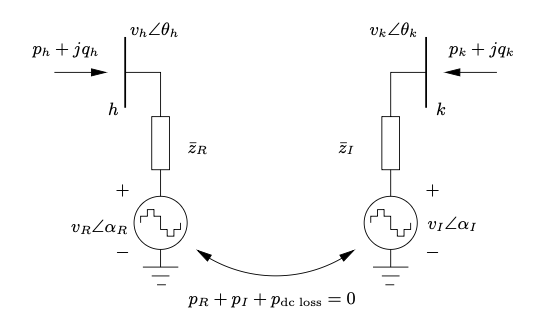
This is a well known model in the literature, however you cannot represent a proper DC grid with it, nor you can simulate contingencies on the DC elements or have more than one cable at a time.
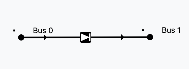
Controls available
The HvdcLine device has only 2 controls: Active power control (Pset) and AC line emulation (free)
Control type |
Effect |
|---|---|
Pset |
Set active power |
free |
AC emulation: |
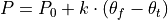
Let’s see a python example using 4 buses:
import VeraGridEngine as vg

# Grid instantiation
grid = vg.MultiCircuit()

# Define buses
bus1 = grid.add_bus(vg.Bus(name='B1', Vnom=135, is_slack=True))
bus2 = grid.add_bus(vg.Bus(name='B2', Vnom=135))
bus5 = grid.add_bus(vg.Bus(name='B5', Vnom=135))
bus6 = grid.add_bus(vg.Bus(name='B6', Vnom=135))

# Define AC lines
line12 = grid.add_line(vg.Line(name='L12', bus_from=bus1, bus_to=bus2, r=0.001, x=0.01))
line25 = grid.add_line(vg.Line(name='L25', bus_from=bus2, bus_to=bus5, r=0.05, x=0.05))
line56 = grid.add_line(vg.Line(name='L56', bus_from=bus5, bus_to=bus6, r=0.001, x=0.01))
line256 = grid.add_line(vg.Line(name='L562', bus_from=bus5, bus_to=bus6, r=0.001, x=0.01))

# Define Hvdc Line
line34 = grid.add_hvdc(vg.HvdcLine(name='L34', bus_from=bus2, bus_to=bus5, Pset=0.2))

# Define generators
grid.add_generator(bus=bus1, api_obj=vg.Generator(name='Gen1', P=1.0, vset=1.01))
grid.add_generator(bus=bus6, api_obj=vg.Generator(name='Gen2', P=1.0, vset=1.02))

# Define loads
grid.add_load(bus=bus2, api_obj=vg.Load(name='Load1', P=3.0, Q=0.3))
grid.add_load(bus=bus5, api_obj=vg.Load(name='Load2', P=2.0, Q=0.5))

# Run power flow
pf_options = vg.PowerFlowOptions(solver_type=vg.SolverType.PowellDogLeg,
                                 retry_with_other_methods=False)
pf_driver = vg.PowerFlowDriver(grid=grid, options=pf_options)
pf_driver.run()

print('Bus values')
print(pf_driver.results.get_bus_df())

print('Branch values')
print(pf_driver.results.get_branch_df())

print("error:", pf_driver.results.error)

vg.save_file(grid, "6bus_a.veragrid")
Registered properties
Profile-enabled properties: active, rate, contingency_factor, protection_rating_factor, Cost, temp_oper, Pset, angle_droop, Vset_f, Vset_t.
name |
class_type |
unit |
mandatory |
max_chars |
descriptions |
has_profile |
comment |
|---|---|---|---|---|---|---|---|
idtag |
str |
False |
Unique ID |
False |
|||
name |
str |
False |
Name of the device. |
False |
|||
code |
str |
False |
Secondary ID |
False |
|||
rdfid |
str |
False |
RDF ID for further compatibility |
False |
|||
action |
enum ActionType |
False |
Object action to perform. Only used for model merging. |
False |
|||
comment |
str |
False |
User comment |
False |
|||
diff_changes |
MergeInformation |
False |
False |
||||
modelling_authority |
Modelling Authority |
False |
Modelling authority of this asset |
False |
|||
commissioned_date |
int |
False |
Commissioned date of the asset |
False |
|||
decommissioned_date |
int |
False |
Decommissioned date of the asset |
False |
|||
build_status |
enum BuildStatus |
False |
Device build status. Used in expansion planning. |
False |
|||
owners |
AssociationsList |
p.u. |
False |
Owners associations to injections |
False |
||
rms_model |
DaeBlock |
False |
RMS dynamic model |
False |
|||
emt_model |
DaeBlock |
False |
EMT dynamic model |
False |
|||
rms_template |
RMS template |
False |
Native RMS template used. Assigning it clears rms_fmu_template. |
False |
|||
emt_template |
EMT template |
False |
Native EMT template used. Assigning it clears emt_fmu_template. |
False |
|||
rms_fmu_template |
FMU template |
False |
RMS FMU template used only by RMS simulations. Assigning it clears rms_template. |
False |
|||
emt_fmu_template |
FMU template |
False |
EMT FMU template used only by EMT simulations. Assigning it clears emt_template. |
False |
|||
rms_fmu_import_config |
str |
False |
Serialized FMU Co-Simulation RMS configuration |
False |
|||
emt_fmu_import_config |
str |
False |
Serialized FMU Co-Simulation EMT configuration |
False |
|||
rms_fmu_me_import_config |
str |
False |
Serialized FMU Model Exchange RMS configuration |
False |
|||
emt_fmu_me_import_config |
str |
False |
Serialized FMU Model Exchange EMT configuration |
False |
|||
bus_from |
Bus |
False |
Name of the bus at the “from” side |
False |
|||
bus_to |
Bus |
False |
Name of the bus at the “to” side |
False |
|||
active |
bool |
False |
Is active? |
True |
|||
reducible |
bool |
False |
Is the branch to be reduced by the topology preprocessor? |
False |
|||
design_rate |
float |
MVA |
False |
Design thermal rating power that is not modified for operational reasons or otherwise |
False |
||
rate |
float |
MVA |
False |
Operational thermal rating power |
True |
||
contingency_factor |
float |
p.u. |
False |
Rating multiplier for contingencies |
True |
||
protection_rating_factor |
float |
p.u. |
False |
Rating multiplier that indicates the maximum flow before the protections tripping |
True |
||
monitor_loading |
bool |
False |
Monitor this device loading for OPF, NTC or contingency studies. |
False |
|||
mttf |
float |
h |
False |
Mean time to failure |
False |
||
mttr |
float |
h |
False |
Mean time to repair |
False |
||
Cost |
float |
e/MWh |
False |
Cost of overloads. Used in OPF |
True |
||
capex |
float |
e/MW |
False |
Cost of investment. Used in expansion planning. |
False |
||
opex |
float |
e/MWh |
False |
Cost of operation. Used in expansion planning. |
False |
||
group |
Branch group |
False |
Group where this branch belongs |
False |
|||
color |
str |
False |
Color to paint the element in the map diagram |
False |
|||
bus_from_pos |
int |
False |
Aid to locate devices on a busbar |
False |
|||
bus_to_pos |
int |
False |
Aid to locate devices on a busbar |
False |
|||
temp_base |
float |
ºC |
False |
Base temperature at which R was measured. |
False |
||
temp_oper |
float |
ºC |
False |
Operation temperature to modify R. |
True |
||
alpha |
float |
1/ºC |
False |
Thermal coefficient to modify R,around a reference temperature using a linear approximation.For example:Copper @ 20ºC: 0.004041,Copper @ 75ºC: 0.00323,Annealed copper @ 20ºC: 0.00393,Aluminum @ 20ºC: 0.004308,Aluminum @ 75ºC: 0.00330 |
False |
||
dispatchable |
bool |
False |
Is the line power optimizable? |
False |
|||
control_mode |
enum HvdcControlType |
- |
False |
Control type. |
False |
||
Pset |
float |
MW |
False |
Set power flow. |
True |
||
r |
float |
Ohm |
False |
line resistance. |
False |
||
dc_link_voltage |
float |
kV |
False |
line voltage (only for compatibility, not used in calcs.) |
False |
||
angle_droop |
float |
MW/deg |
False |
Power/angle rate control |
True |
||
Vset_f |
float |
p.u. |
False |
Set voltage at the from side |
True |
||
Vset_t |
float |
p.u. |
False |
Set voltage at the to side |
True |
||
min_firing_angle_f |
float |
rad |
False |
minimum firing angle at the “from” side. |
False |
||
max_firing_angle_f |
float |
rad |
False |
maximum firing angle at the “from” side. |
False |
||
min_firing_angle_t |
float |
rad |
False |
minimum firing angle at the “to” side. |
False |
||
max_firing_angle_t |
float |
rad |
False |
maximum firing angle at the “to” side. |
False |
||
length |
float |
km |
False |
Length of the branch (not used for calculation) |
False |
||
locations |
Line locations |
False |
False |
VSC
A better way of simulating AC-DC grids is what led us to research the literature for formulations that were complete, correct and explicit. Founding none, we started to create a formulation, by means of introducing how a converter device should behave.
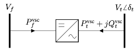
It turns out that a converter cannot be a regular -branch.
It has to be a decoupled branch represented by two injections.
More or less like the 2-generators model: 2 injections plus a coupling equation.
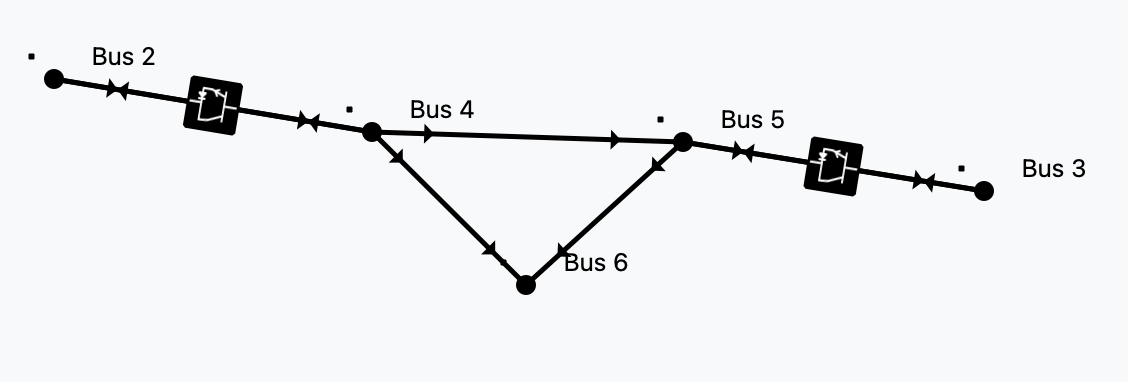
By introducing this type of branch, we get the freedom to represent the AC and DC grids in any level of detail.
Solvability rules
The power flow simulation is an optimization problem formed by equality constraints. Because of this:
For every AC island we must specify one voltage module
 and one voltage angle
  .
Usually, at the so called slack bus.
.
Usually, at the so called slack bus.For every DC island there must be a
set point.
This can be thought of as a DC slack.An AC branch has 4 unknowns (
 )
and 4 equations (
)
and 4 equations ( ).
).A DC branch has 2 unknowns (
 ) and 2 equations
(
) and 2 equations
( ).
).A converter branch has 3 unknowns (
 )
and only 1 natural equation, the losses equation.
That is why every converter must control two magnitudes to
add the 2 extra equations needed.
)
and only 1 natural equation, the losses equation.
That is why every converter must control two magnitudes to
add the 2 extra equations needed.
Since we must ensure equal number of unknowns and equations globally, there is a control compatibility theory.
Controls available
Steaming from the solvability rules, we can introduce the converter controls. For every converter we need to choose 2 controls to ensure solvability.
Control type |
Effect |
|---|---|
|
Voltage module control at the DC side (from side) |
|
Voltage module control at the AC side (to side) |
|
Voltage angle control at the AC side (to side) |
|
Active power control at the AC side (to side) |
|
Reactive power control at the AC side (to side) |
|
Active power control at the DC side (from side) |


Putting it all together
We wanted a no-compromise AC-DC power flow with good convergence properties.
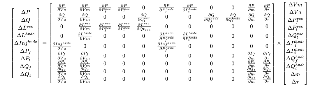
This method was introduced in here and further developed in VeraGrid from 2024 to 2025.
6-bus example
import VeraGridEngine as vg

# Grid instantiation
grid = vg.MultiCircuit()

# Define buses
bus1 = grid.add_bus(vg.Bus(name='B1', Vnom=135, is_slack=True))
bus2 = grid.add_bus(vg.Bus(name='B2', Vnom=135))
bus3 = grid.add_bus(vg.Bus(name='B3', Vnom=100, is_dc=True))
bus4 = grid.add_bus(vg.Bus(name='B4', Vnom=100, is_dc=True))
bus5 = grid.add_bus(vg.Bus(name='B5', Vnom=135))
bus6 = grid.add_bus(vg.Bus(name='B6', Vnom=135))

# Define AC lines
line12 = grid.add_line(vg.Line(name='L12', bus_from=bus1, bus_to=bus2, r=0.001, x=0.1))
line25 = grid.add_line(vg.Line(name='L25', bus_from=bus2, bus_to=bus5, r=1.05, x=0.5))
line56 = grid.add_line(vg.Line(name='L56', bus_from=bus5, bus_to=bus6, r=0.001, x=0.1))
line256 = grid.add_line(vg.Line(name='L562', bus_from=bus5, bus_to=bus6, r=0.001, x=0.1))

# Define DC lines
line34 = grid.add_dc_line(vg.DcLine(name='L34', bus_from=bus3, bus_to=bus4, r=2.05))

# Define VSCs
vsc1 = grid.add_vsc(vg.VSC(name='VSC1', bus_from=bus3, bus_to=bus2,
                           rate=100, alpha1=0.001, alpha2=0.015, alpha3=0.01,
                           control1=vg.ConverterControlType.Vm_ac,
                           control2=vg.ConverterControlType.Pdc,
                           control1_val=1.0333,
                           control2_val=0.2))

vsc2 = grid.add_vsc(vg.VSC(name='VSC2', bus_from=bus4, bus_to=bus5,
                           rate=100, alpha1=0.001, alpha2=0.015, alpha3=0.01,
                           control1=vg.ConverterControlType.Vm_dc,
                           control2=vg.ConverterControlType.Qac,
                           control1_val=1.05,
                           control2_val=-7.21))

# Define generators
grid.add_generator(bus=bus1, api_obj=vg.Generator(name='Gen1', P=1.0, vset=1.01))
grid.add_generator(bus=bus6, api_obj=vg.Generator(name='Gen2', P=1.0, vset=1.02))

# Define loads
grid.add_load(bus=bus2, api_obj=vg.Load(name='Load1', P=3.0, Q=0.3))
grid.add_load(bus=bus5, api_obj=vg.Load(name='Load2', P=2.0, Q=0.5))

# Run power flow
pf_options = vg.PowerFlowOptions(solver_type=vg.SolverType.PowellDogLeg,
                                 retry_with_other_methods=False)
pf_driver = vg.PowerFlowDriver(grid=grid, options=pf_options)
pf_driver.run()

print('Bus values')
print(pf_driver.results.get_bus_df())
print(pf_driver.results.get_bus_df().to_markdown(tablefmt="grid"))

print('Branch values')
print(pf_driver.results.get_branch_df())
print(pf_driver.results.get_branch_df().to_markdown(tablefmt="grid"))

print("error:", pf_driver.results.error)

vg.save_file(grid, "6bus.veragrid")
Vm |
Va |
P |
Q |
|
|---|---|---|---|---|
B1 |
1.01 |
0 |
15.5919 |
-236.815 |
B2 |
1.0333 |
-0.215613 |
-3 |
-0.299984 |
B3 |
1.04608 |
0 |
-0.197999 |
-9.75607e-22 |
B4 |
1.05 |
0 |
0.198741 |
9.79262e-22 |
B5 |
1.02144 |
0.362496 |
-2 |
-0.499983 |
B6 |
1.02 |
0.373325 |
1 |
-29.3828 |
Pf |
Qf |
Pt |
Qt |
loading |
Ploss |
Qloss |
|
|---|---|---|---|---|---|---|---|
L12 |
15.5919 |
-236.815 |
-15.0397 |
242.337 |
1559.19 |
0.552148 |
5.52148 |
L25 |
1.66417 |
22.9626 |
-1.41595 |
-22.7143 |
166.417 |
0.248218 |
0.248218 |
L56 |
-0.497924 |
14.7122 |
0.500001 |
-14.6914 |
-49.7924 |
0.00207697 |
0.0207697 |
L562 |
-0.497924 |
14.7122 |
0.500001 |
-14.6914 |
-49.7924 |
0.00207697 |
0.0207697 |
L34 |
-0.199999 |
-9.75607e-22 |
0.200749 |
9.79262e-22 |
-19.9999 |
0.000749344 |
3.65533e-24 |
Registered properties
Profile-enabled properties: active, rate, contingency_factor, protection_rating_factor, Cost, temp_oper, control1, control1_dev, control1_val, control1_val_droop, control1_droop_val, control2, control2_dev, control2_val, control2_val_droop, control2_droop_val, fault_control.
name |
class_type |
unit |
mandatory |
max_chars |
descriptions |
has_profile |
comment |
|---|---|---|---|---|---|---|---|
idtag |
str |
False |
Unique ID |
False |
|||
name |
str |
False |
Name of the device. |
False |
|||
code |
str |
False |
Secondary ID |
False |
|||
rdfid |
str |
False |
RDF ID for further compatibility |
False |
|||
action |
enum ActionType |
False |
Object action to perform. Only used for model merging. |
False |
|||
comment |
str |
False |
User comment |
False |
|||
diff_changes |
MergeInformation |
False |
False |
||||
modelling_authority |
Modelling Authority |
False |
Modelling authority of this asset |
False |
|||
commissioned_date |
int |
False |
Commissioned date of the asset |
False |
|||
decommissioned_date |
int |
False |
Decommissioned date of the asset |
False |
|||
build_status |
enum BuildStatus |
False |
Device build status. Used in expansion planning. |
False |
|||
owners |
AssociationsList |
p.u. |
False |
Owners associations to injections |
False |
||
rms_model |
DaeBlock |
False |
RMS dynamic model |
False |
|||
emt_model |
DaeBlock |
False |
EMT dynamic model |
False |
|||
rms_template |
RMS template |
False |
Native RMS template used. Assigning it clears rms_fmu_template. |
False |
|||
emt_template |
EMT template |
False |
Native EMT template used. Assigning it clears emt_fmu_template. |
False |
|||
rms_fmu_template |
FMU template |
False |
RMS FMU template used only by RMS simulations. Assigning it clears rms_template. |
False |
|||
emt_fmu_template |
FMU template |
False |
EMT FMU template used only by EMT simulations. Assigning it clears emt_template. |
False |
|||
rms_fmu_import_config |
str |
False |
Serialized FMU Co-Simulation RMS configuration |
False |
|||
emt_fmu_import_config |
str |
False |
Serialized FMU Co-Simulation EMT configuration |
False |
|||
rms_fmu_me_import_config |
str |
False |
Serialized FMU Model Exchange RMS configuration |
False |
|||
emt_fmu_me_import_config |
str |
False |
Serialized FMU Model Exchange EMT configuration |
False |
|||
bus_from |
Bus |
False |
Name of the bus at the “from” side |
False |
|||
bus_to |
Bus |
False |
Name of the bus at the “to” side |
False |
|||
active |
bool |
False |
Is active? |
True |
|||
reducible |
bool |
False |
Is the branch to be reduced by the topology preprocessor? |
False |
|||
design_rate |
float |
MVA |
False |
Design thermal rating power that is not modified for operational reasons or otherwise |
False |
||
rate |
float |
MVA |
False |
Operational thermal rating power |
True |
||
contingency_factor |
float |
p.u. |
False |
Rating multiplier for contingencies |
True |
||
protection_rating_factor |
float |
p.u. |
False |
Rating multiplier that indicates the maximum flow before the protections tripping |
True |
||
monitor_loading |
bool |
False |
Monitor this device loading for OPF, NTC or contingency studies. |
False |
|||
mttf |
float |
h |
False |
Mean time to failure |
False |
||
mttr |
float |
h |
False |
Mean time to repair |
False |
||
Cost |
float |
e/MWh |
False |
Cost of overloads. Used in OPF |
True |
||
capex |
float |
e/MW |
False |
Cost of investment. Used in expansion planning. |
False |
||
opex |
float |
e/MWh |
False |
Cost of operation. Used in expansion planning. |
False |
||
group |
Branch group |
False |
Group where this branch belongs |
False |
|||
color |
str |
False |
Color to paint the element in the map diagram |
False |
|||
bus_from_pos |
int |
False |
Aid to locate devices on a busbar |
False |
|||
bus_to_pos |
int |
False |
Aid to locate devices on a busbar |
False |
|||
temp_base |
float |
ºC |
False |
Base temperature at which R was measured. |
False |
||
temp_oper |
float |
ºC |
False |
Operation temperature to modify R. |
True |
||
alpha |
float |
1/ºC |
False |
Thermal coefficient to modify R,around a reference temperature using a linear approximation.For example:Copper @ 20ºC: 0.004041,Copper @ 75ºC: 0.00323,Annealed copper @ 20ºC: 0.00393,Aluminum @ 20ºC: 0.004308,Aluminum @ 75ºC: 0.00330 |
False |
||
bus_dc_n |
Bus |
False |
DC negative bus |
False |
|||
alpha1 |
float |
False |
Losses constant parameter (IEC 62751-2 loss Correction, idle loss). |
False |
|||
alpha2 |
float |
False |
Losses linear parameter (IEC 62751-2 loss Correction, Switching loss). |
False |
|||
alpha3 |
float |
False |
Losses quadratic parameter (IEC 62751-2 loss Correction, resistive loss). |
False |
|||
control1 |
enum ConverterControlType |
False |
Control mode 1. |
True |
|||
control1_dev |
BusOrBranch |
False |
Controlled device, None to apply to this converter |
True |
|||
control1_val |
float |
False |
Control value 1.p.u. for voltage rad for angles MW for P MVAr for Q |
True |
|||
control1_val_min |
float |
False |
False |
||||
control1_val_max |
float |
False |
False |
||||
control1_val_droop |
float |
False |
True |
||||
control1_droop_val |
float |
False |
True |
||||
control1_droop_val_min |
float |
False |
False |
||||
control1_droop_val_max |
float |
False |
False |
||||
control2 |
enum ConverterControlType |
False |
Control mode 2. |
True |
|||
control2_dev |
BusOrBranch |
False |
Controlled device, None to apply to this converter |
True |
|||
control2_val |
float |
False |
Control value 2.p.u. for voltage rad for angles MW for P MVAr for Q |
True |
|||
control2_val_min |
float |
False |
False |
||||
control2_val_max |
float |
False |
False |
||||
control2_val_droop |
float |
False |
True |
||||
control2_droop_val |
float |
False |
True |
||||
control2_droop_val_min |
float |
False |
False |
||||
control2_droop_val_max |
float |
False |
False |
||||
fault_control |
enum ConverterFaultControlType |
False |
VSC control system during a short-circuit event. |
True |
|||
min_ac_voltage |
float |
p.u. |
False |
Minimum AC voltage threshold. If the AC bus voltage drops below this value, the VSC is disconnected. |
False |
||
ysvs |
float |
p.u. |
False |
Admittance of non-controlled Static Var Systems. |
False |
||
x |
float |
px |
False |
x position |
False |
||
y |
float |
px |
False |
y position |
False |
UPFC
A UPFC models a unified power flow controller embedded in the AC network.
This device links terminals or represents a network element between buses.
Registered properties
Profile-enabled properties: active, rate, contingency_factor, protection_rating_factor, Cost, temp_oper.
name |
class_type |
unit |
mandatory |
max_chars |
descriptions |
has_profile |
comment |
|---|---|---|---|---|---|---|---|
idtag |
str |
False |
Unique ID |
False |
|||
name |
str |
False |
Name of the device. |
False |
|||
code |
str |
False |
Secondary ID |
False |
|||
rdfid |
str |
False |
RDF ID for further compatibility |
False |
|||
action |
enum ActionType |
False |
Object action to perform. Only used for model merging. |
False |
|||
comment |
str |
False |
User comment |
False |
|||
diff_changes |
MergeInformation |
False |
False |
||||
modelling_authority |
Modelling Authority |
False |
Modelling authority of this asset |
False |
|||
commissioned_date |
int |
False |
Commissioned date of the asset |
False |
|||
decommissioned_date |
int |
False |
Decommissioned date of the asset |
False |
|||
build_status |
enum BuildStatus |
False |
Device build status. Used in expansion planning. |
False |
|||
owners |
AssociationsList |
p.u. |
False |
Owners associations to injections |
False |
||
rms_model |
DaeBlock |
False |
RMS dynamic model |
False |
|||
emt_model |
DaeBlock |
False |
EMT dynamic model |
False |
|||
rms_template |
RMS template |
False |
Native RMS template used. Assigning it clears rms_fmu_template. |
False |
|||
emt_template |
EMT template |
False |
Native EMT template used. Assigning it clears emt_fmu_template. |
False |
|||
rms_fmu_template |
FMU template |
False |
RMS FMU template used only by RMS simulations. Assigning it clears rms_template. |
False |
|||
emt_fmu_template |
FMU template |
False |
EMT FMU template used only by EMT simulations. Assigning it clears emt_template. |
False |
|||
rms_fmu_import_config |
str |
False |
Serialized FMU Co-Simulation RMS configuration |
False |
|||
emt_fmu_import_config |
str |
False |
Serialized FMU Co-Simulation EMT configuration |
False |
|||
rms_fmu_me_import_config |
str |
False |
Serialized FMU Model Exchange RMS configuration |
False |
|||
emt_fmu_me_import_config |
str |
False |
Serialized FMU Model Exchange EMT configuration |
False |
|||
bus_from |
Bus |
False |
Name of the bus at the “from” side |
False |
|||
bus_to |
Bus |
False |
Name of the bus at the “to” side |
False |
|||
active |
bool |
False |
Is active? |
True |
|||
reducible |
bool |
False |
Is the branch to be reduced by the topology preprocessor? |
False |
|||
design_rate |
float |
MVA |
False |
Design thermal rating power that is not modified for operational reasons or otherwise |
False |
||
rate |
float |
MVA |
False |
Operational thermal rating power |
True |
||
contingency_factor |
float |
p.u. |
False |
Rating multiplier for contingencies |
True |
||
protection_rating_factor |
float |
p.u. |
False |
Rating multiplier that indicates the maximum flow before the protections tripping |
True |
||
monitor_loading |
bool |
False |
Monitor this device loading for OPF, NTC or contingency studies. |
False |
|||
mttf |
float |
h |
False |
Mean time to failure |
False |
||
mttr |
float |
h |
False |
Mean time to repair |
False |
||
Cost |
float |
e/MWh |
False |
Cost of overloads. Used in OPF |
True |
||
capex |
float |
e/MW |
False |
Cost of investment. Used in expansion planning. |
False |
||
opex |
float |
e/MWh |
False |
Cost of operation. Used in expansion planning. |
False |
||
group |
Branch group |
False |
Group where this branch belongs |
False |
|||
color |
str |
False |
Color to paint the element in the map diagram |
False |
|||
bus_from_pos |
int |
False |
Aid to locate devices on a busbar |
False |
|||
bus_to_pos |
int |
False |
Aid to locate devices on a busbar |
False |
|||
temp_base |
float |
ºC |
False |
Base temperature at which R was measured. |
False |
||
temp_oper |
float |
ºC |
False |
Operation temperature to modify R. |
True |
||
alpha |
float |
1/ºC |
False |
Thermal coefficient to modify R,around a reference temperature using a linear approximation.For example:Copper @ 20ºC: 0.004041,Copper @ 75ºC: 0.00323,Annealed copper @ 20ºC: 0.00393,Aluminum @ 20ºC: 0.004308,Aluminum @ 75ºC: 0.00330 |
False |
||
R |
float |
p.u. |
False |
Series positive sequence resistance. |
False |
||
X |
float |
p.u. |
False |
Series positive sequence reactance. |
False |
||
Rsh |
float |
p.u. |
False |
Shunt positive sequence resistance. |
False |
||
Xsh |
float |
p.u. |
False |
Shunt positive sequence resistance. |
False |
||
R0 |
float |
p.u. |
False |
Series zero sequence resistance. |
False |
||
X0 |
float |
p.u. |
False |
Series zero sequence reactance. |
False |
||
Rsh0 |
float |
p.u. |
False |
Shunt zero sequence resistance. |
False |
||
Xsh0 |
float |
p.u. |
False |
Shunt zero sequence resistance. |
False |
||
R2 |
float |
p.u. |
False |
Series negative sequence resistance. |
False |
||
X2 |
float |
p.u. |
False |
Series negative sequence reactance. |
False |
||
Rsh2 |
float |
p.u. |
False |
Shunt negative sequence resistance. |
False |
||
Xsh2 |
float |
p.u. |
False |
Shunt negative sequence resistance. |
False |
||
Vsh |
float |
p.u. |
False |
Shunt voltage set point. |
False |
||
Pfset |
float |
MW |
False |
Active power set point. |
False |
||
Qfset |
float |
MVAr |
False |
Active power set point. |
False |
Switch
A Switch models a topological switching element that can open or close network connectivity.
This device links terminals or represents a network element between buses.
Registered properties
Profile-enabled properties: active, rate, contingency_factor, protection_rating_factor, Cost, temp_oper.
name |
class_type |
unit |
mandatory |
max_chars |
descriptions |
has_profile |
comment |
|---|---|---|---|---|---|---|---|
idtag |
str |
False |
Unique ID |
False |
|||
name |
str |
False |
Name of the device. |
False |
|||
code |
str |
False |
Secondary ID |
False |
|||
rdfid |
str |
False |
RDF ID for further compatibility |
False |
|||
action |
enum ActionType |
False |
Object action to perform. Only used for model merging. |
False |
|||
comment |
str |
False |
User comment |
False |
|||
diff_changes |
MergeInformation |
False |
False |
||||
modelling_authority |
Modelling Authority |
False |
Modelling authority of this asset |
False |
|||
commissioned_date |
int |
False |
Commissioned date of the asset |
False |
|||
decommissioned_date |
int |
False |
Decommissioned date of the asset |
False |
|||
build_status |
enum BuildStatus |
False |
Device build status. Used in expansion planning. |
False |
|||
owners |
AssociationsList |
p.u. |
False |
Owners associations to injections |
False |
||
rms_model |
DaeBlock |
False |
RMS dynamic model |
False |
|||
emt_model |
DaeBlock |
False |
EMT dynamic model |
False |
|||
rms_template |
RMS template |
False |
Native RMS template used. Assigning it clears rms_fmu_template. |
False |
|||
emt_template |
EMT template |
False |
Native EMT template used. Assigning it clears emt_fmu_template. |
False |
|||
rms_fmu_template |
FMU template |
False |
RMS FMU template used only by RMS simulations. Assigning it clears rms_template. |
False |
|||
emt_fmu_template |
FMU template |
False |
EMT FMU template used only by EMT simulations. Assigning it clears emt_template. |
False |
|||
rms_fmu_import_config |
str |
False |
Serialized FMU Co-Simulation RMS configuration |
False |
|||
emt_fmu_import_config |
str |
False |
Serialized FMU Co-Simulation EMT configuration |
False |
|||
rms_fmu_me_import_config |
str |
False |
Serialized FMU Model Exchange RMS configuration |
False |
|||
emt_fmu_me_import_config |
str |
False |
Serialized FMU Model Exchange EMT configuration |
False |
|||
bus_from |
Bus |
False |
Name of the bus at the “from” side |
False |
|||
bus_to |
Bus |
False |
Name of the bus at the “to” side |
False |
|||
active |
bool |
False |
Is active? |
True |
|||
reducible |
bool |
False |
Is the branch to be reduced by the topology preprocessor? |
False |
|||
design_rate |
float |
MVA |
False |
Design thermal rating power that is not modified for operational reasons or otherwise |
False |
||
rate |
float |
MVA |
False |
Operational thermal rating power |
True |
||
contingency_factor |
float |
p.u. |
False |
Rating multiplier for contingencies |
True |
||
protection_rating_factor |
float |
p.u. |
False |
Rating multiplier that indicates the maximum flow before the protections tripping |
True |
||
monitor_loading |
bool |
False |
Monitor this device loading for OPF, NTC or contingency studies. |
False |
|||
mttf |
float |
h |
False |
Mean time to failure |
False |
||
mttr |
float |
h |
False |
Mean time to repair |
False |
||
Cost |
float |
e/MWh |
False |
Cost of overloads. Used in OPF |
True |
||
capex |
float |
e/MW |
False |
Cost of investment. Used in expansion planning. |
False |
||
opex |
float |
e/MWh |
False |
Cost of operation. Used in expansion planning. |
False |
||
group |
Branch group |
False |
Group where this branch belongs |
False |
|||
color |
str |
False |
Color to paint the element in the map diagram |
False |
|||
bus_from_pos |
int |
False |
Aid to locate devices on a busbar |
False |
|||
bus_to_pos |
int |
False |
Aid to locate devices on a busbar |
False |
|||
temp_base |
float |
ºC |
False |
Base temperature at which R was measured. |
False |
||
temp_oper |
float |
ºC |
False |
Operation temperature to modify R. |
True |
||
alpha |
float |
1/ºC |
False |
Thermal coefficient to modify R,around a reference temperature using a linear approximation.For example:Copper @ 20ºC: 0.004041,Copper @ 75ºC: 0.00323,Annealed copper @ 20ºC: 0.00393,Aluminum @ 20ºC: 0.004308,Aluminum @ 75ºC: 0.00330 |
False |
||
R |
float |
pu |
False |
Positive-sequence resistance |
False |
||
X |
float |
pu |
False |
Positive-sequence reactance |
False |
||
retained |
bool |
False |
Switch is retained |
False |
|||
normal_open |
bool |
False |
Normal position of the switch |
False |
|||
rated_current |
float |
kA |
False |
Rated current of the switch device. |
False |
||
graphic_type |
enum SwitchGraphicType |
False |
Graphic to use in the schematic. |
False |
Wire
A Wire stores conductor parameters used by overhead-line templates and geometry-based line calculations.
This device stores reusable equipment data that can be applied to physical network elements.
Registered properties
Profile-enabled properties: none.
name |
class_type |
unit |
mandatory |
max_chars |
descriptions |
has_profile |
comment |
|---|---|---|---|---|---|---|---|
idtag |
str |
False |
Unique ID |
False |
|||
name |
str |
False |
Name of the device. |
False |
|||
code |
str |
False |
Secondary ID |
False |
|||
rdfid |
str |
False |
RDF ID for further compatibility |
False |
|||
action |
enum ActionType |
False |
Object action to perform. Only used for model merging. |
False |
|||
comment |
str |
False |
User comment |
False |
|||
diff_changes |
MergeInformation |
False |
False |
||||
R |
float |
Ohm/km |
False |
resistance of the conductor |
False |
||
diameter |
float |
mm |
False |
Diameter of wire |
False |
||
diameter_internal |
float |
mm |
False |
Internal radius of the conductor |
False |
||
is_tube |
bool |
False |
Is it a tubular conductor? |
False |
|||
max_current |
float |
kA |
False |
Maximum current of the conductor |
False |
||
stranding |
str |
False |
Stranding of wire |
False |
|||
material |
str |
False |
Material of wire |
False |
OverheadLineType
An OverheadLineType stores reusable conductor geometry and the derived impedance and admittance matrices for overhead lines.
This device stores reusable equipment data that can be applied to physical network elements.
Registered properties
Profile-enabled properties: none.
name |
class_type |
unit |
mandatory |
max_chars |
descriptions |
has_profile |
comment |
|---|---|---|---|---|---|---|---|
idtag |
str |
False |
Unique ID |
False |
|||
name |
str |
False |
Name of the device. |
False |
|||
code |
str |
False |
Secondary ID |
False |
|||
rdfid |
str |
False |
RDF ID for further compatibility |
False |
|||
action |
enum ActionType |
False |
Object action to perform. Only used for model merging. |
False |
|||
comment |
str |
False |
User comment |
False |
|||
diff_changes |
MergeInformation |
False |
False |
||||
modelling_authority |
Modelling Authority |
False |
Modelling authority of this asset |
False |
|||
commissioned_date |
int |
False |
Commissioned date of the asset |
False |
|||
decommissioned_date |
int |
False |
Decommissioned date of the asset |
False |
|||
build_status |
enum BuildStatus |
False |
Device build status. Used in expansion planning. |
False |
|||
owners |
AssociationsList |
p.u. |
False |
Owners associations to injections |
False |
||
rms_model |
DaeBlock |
False |
RMS dynamic model |
False |
|||
emt_model |
DaeBlock |
False |
EMT dynamic model |
False |
|||
rms_template |
RMS template |
False |
Native RMS template used. Assigning it clears rms_fmu_template. |
False |
|||
emt_template |
EMT template |
False |
Native EMT template used. Assigning it clears emt_fmu_template. |
False |
|||
rms_fmu_template |
FMU template |
False |
RMS FMU template used only by RMS simulations. Assigning it clears rms_template. |
False |
|||
emt_fmu_template |
FMU template |
False |
EMT FMU template used only by EMT simulations. Assigning it clears emt_template. |
False |
|||
rms_fmu_import_config |
str |
False |
Serialized FMU Co-Simulation RMS configuration |
False |
|||
emt_fmu_import_config |
str |
False |
Serialized FMU Co-Simulation EMT configuration |
False |
|||
rms_fmu_me_import_config |
str |
False |
Serialized FMU Model Exchange RMS configuration |
False |
|||
emt_fmu_me_import_config |
str |
False |
Serialized FMU Model Exchange EMT configuration |
False |
|||
earth_resistivity |
float |
Ohm/m3 |
False |
Earth resistivity |
False |
||
frequency |
float |
Hz |
False |
Frequency |
False |
||
Vnom |
float |
kV |
False |
Voltage rating of the line |
False |
||
wires_in_tower |
ListOfWires |
False |
List of wires |
False |
|||
capex |
float |
currency/km |
False |
Capital expenditure per km |
False |
||
opex |
float |
currency/MWh |
False |
Operational expenditure |
False |
UndergroundLineType
An UndergroundLineType stores reusable cable data for underground line modelling.
This device stores reusable equipment data that can be applied to physical network elements.
Registered properties
Profile-enabled properties: none.
name |
class_type |
unit |
mandatory |
max_chars |
descriptions |
has_profile |
comment |
|---|---|---|---|---|---|---|---|
idtag |
str |
False |
Unique ID |
False |
|||
name |
str |
False |
Name of the device. |
False |
|||
code |
str |
False |
Secondary ID |
False |
|||
rdfid |
str |
False |
RDF ID for further compatibility |
False |
|||
action |
enum ActionType |
False |
Object action to perform. Only used for model merging. |
False |
|||
comment |
str |
False |
User comment |
False |
|||
diff_changes |
MergeInformation |
False |
False |
||||
modelling_authority |
Modelling Authority |
False |
Modelling authority of this asset |
False |
|||
commissioned_date |
int |
False |
Commissioned date of the asset |
False |
|||
decommissioned_date |
int |
False |
Decommissioned date of the asset |
False |
|||
build_status |
enum BuildStatus |
False |
Device build status. Used in expansion planning. |
False |
|||
owners |
AssociationsList |
p.u. |
False |
Owners associations to injections |
False |
||
rms_model |
DaeBlock |
False |
RMS dynamic model |
False |
|||
emt_model |
DaeBlock |
False |
EMT dynamic model |
False |
|||
rms_template |
RMS template |
False |
Native RMS template used. Assigning it clears rms_fmu_template. |
False |
|||
emt_template |
EMT template |
False |
Native EMT template used. Assigning it clears emt_fmu_template. |
False |
|||
rms_fmu_template |
FMU template |
False |
RMS FMU template used only by RMS simulations. Assigning it clears rms_template. |
False |
|||
emt_fmu_template |
FMU template |
False |
EMT FMU template used only by EMT simulations. Assigning it clears emt_template. |
False |
|||
rms_fmu_import_config |
str |
False |
Serialized FMU Co-Simulation RMS configuration |
False |
|||
emt_fmu_import_config |
str |
False |
Serialized FMU Co-Simulation EMT configuration |
False |
|||
rms_fmu_me_import_config |
str |
False |
Serialized FMU Model Exchange RMS configuration |
False |
|||
emt_fmu_me_import_config |
str |
False |
Serialized FMU Model Exchange EMT configuration |
False |
|||
Imax |
float |
kA |
False |
Current rating of the line |
False |
||
Vnom |
float |
kV |
False |
Voltage rating of the line |
False |
||
freq |
float |
Hz |
False |
Cable frequency |
False |
||
R |
float |
Ohm/km |
False |
Positive-sequence resistance per km |
False |
||
X |
float |
Ohm/km |
False |
Positive-sequence reactance per km |
False |
||
B |
float |
uS/km |
False |
Positive-sequence shunt susceptance per km |
False |
||
C |
float |
uF/km |
False |
Positive-sequence shunt capacitance per km (alternative to B |
False |
||
R0 |
float |
Ohm/km |
False |
Zero-sequence resistance per km |
False |
||
X0 |
float |
Ohm/km |
False |
Zero-sequence reactance per km |
False |
||
B0 |
float |
uS/km |
False |
Zero-sequence shunt susceptance per km |
False |
||
C0 |
float |
uF/km |
False |
Zero-sequence shunt capacitance per km (alternative to B0 |
False |
||
n_circuits |
int |
False |
number of circuits |
False |
|||
capex |
float |
currency/km |
False |
Capital expenditure per km |
False |
||
opex |
float |
currency/MWh |
False |
Operational expenditure |
False |
SequenceLineType
A SequenceLineType stores reusable positive-, negative-, and zero-sequence branch data.
This device stores reusable equipment data that can be applied to physical network elements.
Registered properties
Profile-enabled properties: none.
name |
class_type |
unit |
mandatory |
max_chars |
descriptions |
has_profile |
comment |
|---|---|---|---|---|---|---|---|
idtag |
str |
False |
Unique ID |
False |
|||
name |
str |
False |
Name of the device. |
False |
|||
code |
str |
False |
Secondary ID |
False |
|||
rdfid |
str |
False |
RDF ID for further compatibility |
False |
|||
action |
enum ActionType |
False |
Object action to perform. Only used for model merging. |
False |
|||
comment |
str |
False |
User comment |
False |
|||
diff_changes |
MergeInformation |
False |
False |
||||
modelling_authority |
Modelling Authority |
False |
Modelling authority of this asset |
False |
|||
commissioned_date |
int |
False |
Commissioned date of the asset |
False |
|||
decommissioned_date |
int |
False |
Decommissioned date of the asset |
False |
|||
build_status |
enum BuildStatus |
False |
Device build status. Used in expansion planning. |
False |
|||
owners |
AssociationsList |
p.u. |
False |
Owners associations to injections |
False |
||
rms_model |
DaeBlock |
False |
RMS dynamic model |
False |
|||
emt_model |
DaeBlock |
False |
EMT dynamic model |
False |
|||
rms_template |
RMS template |
False |
Native RMS template used. Assigning it clears rms_fmu_template. |
False |
|||
emt_template |
EMT template |
False |
Native EMT template used. Assigning it clears emt_fmu_template. |
False |
|||
rms_fmu_template |
FMU template |
False |
RMS FMU template used only by RMS simulations. Assigning it clears rms_template. |
False |
|||
emt_fmu_template |
FMU template |
False |
EMT FMU template used only by EMT simulations. Assigning it clears emt_template. |
False |
|||
rms_fmu_import_config |
str |
False |
Serialized FMU Co-Simulation RMS configuration |
False |
|||
emt_fmu_import_config |
str |
False |
Serialized FMU Co-Simulation EMT configuration |
False |
|||
rms_fmu_me_import_config |
str |
False |
Serialized FMU Model Exchange RMS configuration |
False |
|||
emt_fmu_me_import_config |
str |
False |
Serialized FMU Model Exchange EMT configuration |
False |
|||
Imax |
float |
kA |
False |
Current rating of the line |
False |
||
Vnom |
float |
kV |
False |
Voltage rating of the line |
False |
||
R |
float |
Ohm/km |
False |
Positive-sequence resistance per km |
False |
||
X |
float |
Ohm/km |
False |
Positive-sequence reactance per km |
False |
||
B |
float |
uS/km |
False |
Positive-sequence shunt susceptance per km |
False |
||
R0 |
float |
Ohm/km |
False |
Zero-sequence resistance per km |
False |
||
X0 |
float |
Ohm/km |
False |
Zero-sequence reactance per km |
False |
||
B0 |
float |
uS/km |
False |
Zero-sequence shunt susceptance per km |
False |
||
Cnf |
float |
nF/km |
False |
Positive-sequence shunt conductance per km |
False |
||
Cnf0 |
float |
nF/km |
False |
Zero-sequence shunt conductance per km |
False |
||
use_conductance |
bool |
False |
Use conductance? else the susceptance is used |
False |
|||
n_circuits |
int |
False |
number of circuits |
False |
|||
capex |
float |
currency/km |
False |
Capital expenditure per km |
False |
||
opex |
float |
currency/MWh |
False |
Operational expenditure |
False |
TransformerType
A TransformerType stores reusable nameplate and test-sheet data that can be applied to transformer objects.
This device stores reusable equipment data that can be applied to physical network elements.
Registered properties
Profile-enabled properties: none.
name |
class_type |
unit |
mandatory |
max_chars |
descriptions |
has_profile |
comment |
|---|---|---|---|---|---|---|---|
idtag |
str |
False |
Unique ID |
False |
|||
name |
str |
False |
Name of the device. |
False |
|||
code |
str |
False |
Secondary ID |
False |
|||
rdfid |
str |
False |
RDF ID for further compatibility |
False |
|||
action |
enum ActionType |
False |
Object action to perform. Only used for model merging. |
False |
|||
comment |
str |
False |
User comment |
False |
|||
diff_changes |
MergeInformation |
False |
False |
||||
modelling_authority |
Modelling Authority |
False |
Modelling authority of this asset |
False |
|||
commissioned_date |
int |
False |
Commissioned date of the asset |
False |
|||
decommissioned_date |
int |
False |
Decommissioned date of the asset |
False |
|||
build_status |
enum BuildStatus |
False |
Device build status. Used in expansion planning. |
False |
|||
owners |
AssociationsList |
p.u. |
False |
Owners associations to injections |
False |
||
rms_model |
DaeBlock |
False |
RMS dynamic model |
False |
|||
emt_model |
DaeBlock |
False |
EMT dynamic model |
False |
|||
rms_template |
RMS template |
False |
Native RMS template used. Assigning it clears rms_fmu_template. |
False |
|||
emt_template |
EMT template |
False |
Native EMT template used. Assigning it clears emt_fmu_template. |
False |
|||
rms_fmu_template |
FMU template |
False |
RMS FMU template used only by RMS simulations. Assigning it clears rms_template. |
False |
|||
emt_fmu_template |
FMU template |
False |
EMT FMU template used only by EMT simulations. Assigning it clears emt_template. |
False |
|||
rms_fmu_import_config |
str |
False |
Serialized FMU Co-Simulation RMS configuration |
False |
|||
emt_fmu_import_config |
str |
False |
Serialized FMU Co-Simulation EMT configuration |
False |
|||
rms_fmu_me_import_config |
str |
False |
Serialized FMU Model Exchange RMS configuration |
False |
|||
emt_fmu_me_import_config |
str |
False |
Serialized FMU Model Exchange EMT configuration |
False |
|||
HV |
float |
kV |
False |
Nominal voltage al the high voltage side |
False |
||
LV |
float |
kV |
False |
Nominal voltage al the low voltage side |
False |
||
Sn |
float |
MVA |
False |
Nominal power |
False |
||
Pcu |
float |
kW |
False |
Copper losses |
False |
||
Pfe |
float |
kW |
False |
Iron losses |
False |
||
I0 |
float |
% |
False |
No-load current |
False |
||
Vsc |
float |
% |
False |
Short-circuit voltage |
False |
||
capex |
float |
currency |
False |
Capital expenditure |
False |
||
opex |
float |
currency/MWh |
False |
Operational expenditure |
False |
||
tc_type |
enum TapChangerTypes |
False |
Regulation type |
False |
|||
total_positions |
int |
False |
Number of tap positions |
False |
|||
dV |
float |
p.u. |
False |
Voltage increment per step |
False |
||
neutral_position |
int |
False |
neutral position counting from zero |
False |
|||
asymmetry_angle |
float |
deg |
False |
Asymmetry_angle |
False |
||
conn_hv |
enum WindingType |
False |
Winding 3 phase connection at the from side |
False |
|||
conn_lv |
enum WindingType |
False |
Winding 3 phase connection at the to side |
False |
|||
vector_group_number |
int |
False |
Vector group number. It indicates the structural phase:phase = vector_group_number · 30º |
False |
|||
tap_module_min |
float |
p.u. |
False |
Min tap module |
False |
||
tap_module_max |
float |
p.u. |
False |
Max tap module |
False |
||
tap_phase_min |
float |
rad |
False |
Min tap phase |
False |
||
tap_phase_max |
float |
rad |
False |
Max tap phase |
False |
BranchGroup
A BranchGroup organizes network branches into study or ownership groupings.
This device organizes assets for modelling, ownership, filtering, or reporting.
Registered properties
Profile-enabled properties: none.
name |
class_type |
unit |
mandatory |
max_chars |
descriptions |
has_profile |
comment |
|---|---|---|---|---|---|---|---|
idtag |
str |
False |
Unique ID |
False |
|||
name |
str |
False |
Name of the device. |
False |
|||
code |
str |
False |
Secondary ID |
False |
|||
rdfid |
str |
False |
RDF ID for further compatibility |
False |
|||
action |
enum ActionType |
False |
Object action to perform. Only used for model merging. |
False |
|||
comment |
str |
False |
User comment |
False |
|||
diff_changes |
MergeInformation |
False |
False |
||||
group_type |
enum BranchGroupTypes |
False |
Type of branch group |
False |
|||
color |
str |
False |
Color to paint |
False |
Facility
A Facility groups assets that belong to the same site or installation.
This device organizes assets for modelling, ownership, filtering, or reporting.
Registered properties
Profile-enabled properties: none.
name |
class_type |
unit |
mandatory |
max_chars |
descriptions |
has_profile |
comment |
|---|---|---|---|---|---|---|---|
idtag |
str |
False |
Unique ID |
False |
|||
name |
str |
False |
Name of the device. |
False |
|||
code |
str |
False |
Secondary ID |
False |
|||
rdfid |
str |
False |
RDF ID for further compatibility |
False |
|||
action |
enum ActionType |
False |
Object action to perform. Only used for model merging. |
False |
|||
comment |
str |
False |
User comment |
False |
|||
diff_changes |
MergeInformation |
False |
False |
||||
longitude |
float |
deg |
False |
longitude. |
False |
||
latitude |
float |
deg |
False |
latitude. |
False |
||
color |
str |
False |
Color to paint the element in the map diagram |
False |
Technology
A Technology is a reusable association used to tag injections and assets by technology type.
This device is used as reusable metadata that other assets can reference through associations.
Registered properties
Profile-enabled properties: none.
name |
class_type |
unit |
mandatory |
max_chars |
descriptions |
has_profile |
comment |
|---|---|---|---|---|---|---|---|
idtag |
str |
False |
Unique ID |
False |
|||
name |
str |
False |
Name of the device. |
False |
|||
code |
str |
False |
Secondary ID |
False |
|||
rdfid |
str |
False |
RDF ID for further compatibility |
False |
|||
action |
enum ActionType |
False |
Object action to perform. Only used for model merging. |
False |
|||
comment |
str |
False |
User comment |
False |
|||
diff_changes |
MergeInformation |
False |
False |
||||
name2 |
str |
False |
Name 2 of the technology |
False |
|||
name3 |
str |
False |
Name 3 of the technology |
False |
|||
name4 |
str |
False |
Name 4 of the technology |
False |
|||
color |
str |
False |
Color to paint |
False |
Fuel
A Fuel is a reusable association used to tag generating assets by fuel type.
This device is used as reusable metadata that other assets can reference through associations.
Registered properties
Profile-enabled properties: cost.
name |
class_type |
unit |
mandatory |
max_chars |
descriptions |
has_profile |
comment |
|---|---|---|---|---|---|---|---|
idtag |
str |
False |
Unique ID |
False |
|||
name |
str |
False |
Name of the device. |
False |
|||
code |
str |
False |
Secondary ID |
False |
|||
rdfid |
str |
False |
RDF ID for further compatibility |
False |
|||
action |
enum ActionType |
False |
Object action to perform. Only used for model merging. |
False |
|||
comment |
str |
False |
User comment |
False |
|||
diff_changes |
MergeInformation |
False |
False |
||||
cost |
float |
e/t |
False |
Cost of fuel (e / ton) |
True |
||
color |
str |
False |
Color to paint |
False |
EmissionGas
An EmissionGas is a reusable association used to tag emitting assets for planning and reporting.
This device is used as reusable metadata that other assets can reference through associations.
Registered properties
Profile-enabled properties: cost.
name |
class_type |
unit |
mandatory |
max_chars |
descriptions |
has_profile |
comment |
|---|---|---|---|---|---|---|---|
idtag |
str |
False |
Unique ID |
False |
|||
name |
str |
False |
Name of the device. |
False |
|||
code |
str |
False |
Secondary ID |
False |
|||
rdfid |
str |
False |
RDF ID for further compatibility |
False |
|||
action |
enum ActionType |
False |
Object action to perform. Only used for model merging. |
False |
|||
comment |
str |
False |
User comment |
False |
|||
diff_changes |
MergeInformation |
False |
False |
||||
cost |
float |
e/t |
False |
Cost of emissions (e / ton) |
True |
||
color |
str |
False |
Color to paint |
False |
Owner
An Owner is a reusable association attached to assets through ownership lists.
This device is used as reusable metadata that other assets can reference through associations.
Registered properties
Profile-enabled properties: none.
name |
class_type |
unit |
mandatory |
max_chars |
descriptions |
has_profile |
comment |
|---|---|---|---|---|---|---|---|
idtag |
str |
False |
Unique ID |
False |
|||
name |
str |
False |
Name of the device. |
False |
|||
code |
str |
False |
Secondary ID |
False |
|||
rdfid |
str |
False |
RDF ID for further compatibility |
False |
|||
action |
enum ActionType |
False |
Object action to perform. Only used for model merging. |
False |
|||
comment |
str |
False |
User comment |
False |
|||
diff_changes |
MergeInformation |
False |
False |
||||
address |
str |
False |
Owner address |
False |
|||
color |
str |
False |
Color to paint |
False |
ContingencyGroup
A ContingencyGroup groups related contingency actions into a reusable study set.
This device defines study events, outages, switching actions, or remedial actions.
Registered properties
Profile-enabled properties: none.
name |
class_type |
unit |
mandatory |
max_chars |
descriptions |
has_profile |
comment |
|---|---|---|---|---|---|---|---|
idtag |
str |
False |
Unique ID |
False |
|||
name |
str |
False |
Name of the device. |
False |
|||
code |
str |
False |
Secondary ID |
False |
|||
rdfid |
str |
False |
RDF ID for further compatibility |
False |
|||
action |
enum ActionType |
False |
Object action to perform. Only used for model merging. |
False |
|||
comment |
str |
False |
User comment |
False |
|||
diff_changes |
MergeInformation |
False |
False |
||||
category |
str |
False |
Some tag to category the contingency group |
False |
|||
active |
bool |
False |
Is the contingency group active for consideration? |
False |
Contingency
A Contingency describes one outage or operational change applied during contingency analysis.
This device defines study events, outages, switching actions, or remedial actions.
Registered properties
Profile-enabled properties: none.
name |
class_type |
unit |
mandatory |
max_chars |
descriptions |
has_profile |
comment |
|---|---|---|---|---|---|---|---|
idtag |
str |
False |
Unique ID |
False |
|||
name |
str |
False |
Name of the device. |
False |
|||
code |
str |
False |
Secondary ID |
False |
|||
rdfid |
str |
False |
RDF ID for further compatibility |
False |
|||
action |
enum ActionType |
False |
Object action to perform. Only used for model merging. |
False |
|||
comment |
str |
False |
User comment |
False |
|||
diff_changes |
MergeInformation |
False |
False |
||||
device_idtag |
str |
False |
Unique ID |
False |
|||
tpe |
enum DeviceType |
False |
Device type |
False |
|||
device_name |
str |
False |
Device name |
False |
|||
prop |
enum ContingencyOperationTypes |
False |
Object property to change |
False |
|||
value |
float |
False |
Property value |
False |
|||
group |
Contingency Group |
False |
Contingency group |
False |
RemedialActionGroup
A RemedialActionGroup groups corrective actions that may be applied after a contingency.
This device defines study events, outages, switching actions, or remedial actions.
Registered properties
Profile-enabled properties: none.
name |
class_type |
unit |
mandatory |
max_chars |
descriptions |
has_profile |
comment |
|---|---|---|---|---|---|---|---|
idtag |
str |
False |
Unique ID |
False |
|||
name |
str |
False |
Name of the device. |
False |
|||
code |
str |
False |
Secondary ID |
False |
|||
rdfid |
str |
False |
RDF ID for further compatibility |
False |
|||
action |
enum ActionType |
False |
Object action to perform. Only used for model merging. |
False |
|||
comment |
str |
False |
User comment |
False |
|||
diff_changes |
MergeInformation |
False |
False |
||||
category |
str |
False |
Some tag to category the contingency group |
False |
|||
conn_group |
Contingency Group |
False |
Contingency group |
False |
RemedialAction
A RemedialAction defines one corrective control or switching action.
This device defines study events, outages, switching actions, or remedial actions.
Registered properties
Profile-enabled properties: none.
name |
class_type |
unit |
mandatory |
max_chars |
descriptions |
has_profile |
comment |
|---|---|---|---|---|---|---|---|
idtag |
str |
False |
Unique ID |
False |
|||
name |
str |
False |
Name of the device. |
False |
|||
code |
str |
False |
Secondary ID |
False |
|||
rdfid |
str |
False |
RDF ID for further compatibility |
False |
|||
action |
enum ActionType |
False |
Object action to perform. Only used for model merging. |
False |
|||
comment |
str |
False |
User comment |
False |
|||
diff_changes |
MergeInformation |
False |
False |
||||
device_idtag |
str |
False |
Unique ID |
False |
|||
tpe |
enum DeviceType |
False |
Device type |
False |
|||
device_name |
str |
False |
Device name |
False |
|||
prop |
enum ContingencyOperationTypes |
False |
Object property to change |
False |
|||
value |
float |
False |
Property value |
False |
|||
group |
Remedial action Group |
False |
Remedial action group |
False |
ShortCircuitEvent
A ShortCircuitEvent defines a fault event for short-circuit calculations.
This device defines study events, outages, switching actions, or remedial actions.
Registered properties
Profile-enabled properties: none.
name |
class_type |
unit |
mandatory |
max_chars |
descriptions |
has_profile |
comment |
|---|---|---|---|---|---|---|---|
idtag |
str |
False |
Unique ID |
False |
|||
name |
str |
False |
Name of the device. |
False |
|||
code |
str |
False |
Secondary ID |
False |
|||
rdfid |
str |
False |
RDF ID for further compatibility |
False |
|||
action |
enum ActionType |
False |
Object action to perform. Only used for model merging. |
False |
|||
comment |
str |
False |
User comment |
False |
|||
diff_changes |
MergeInformation |
False |
False |
||||
device_idtag |
str |
False |
Unique ID |
False |
|||
tpe |
enum DeviceType |
False |
Device type |
False |
|||
device_name |
str |
False |
Device name |
False |
|||
fault_type |
enum FaultType |
False |
Type of short circuit |
False |
|||
method |
enum MethodShortCircuit |
False |
Method of short circuit |
False |
|||
phases |
enum PhasesShortCircuit |
False |
Phases involved |
False |
|||
active |
bool |
False |
If true the short-circuit activates when calculated, otherwise is deactivated. |
False |
|||
r_fault |
float |
p.u. |
False |
Resistance of the fault.This is used for short circuit studies. |
False |
||
x_fault |
float |
p.u. |
False |
Reactance of the fault.This is used for short circuit studies. |
False |
InvestmentsGroup
An InvestmentsGroup groups expansion candidates into reusable planning sets.
This device is used by expansion-planning and candidate-investment workflows.
Registered properties
Profile-enabled properties: none.
name |
class_type |
unit |
mandatory |
max_chars |
descriptions |
has_profile |
comment |
|---|---|---|---|---|---|---|---|
idtag |
str |
False |
Unique ID |
False |
|||
name |
str |
False |
Name of the device. |
False |
|||
code |
str |
False |
Secondary ID |
False |
|||
rdfid |
str |
False |
RDF ID for further compatibility |
False |
|||
action |
enum ActionType |
False |
Object action to perform. Only used for model merging. |
False |
|||
comment |
str |
False |
User comment |
False |
|||
diff_changes |
MergeInformation |
False |
False |
||||
category |
str |
False |
Some tag to category the investment group |
False |
|||
discount_rate |
float |
% |
False |
Investment group discount rate |
False |
||
CAPEX |
float |
€ |
False |
Capital Expenditure of the group (added to the individual investments’ capex) |
False |
||
color |
str |
False |
Color to paint |
False |
Investment
An Investment defines one candidate asset action for expansion planning.
This device is used by expansion-planning and candidate-investment workflows.
Registered properties
Profile-enabled properties: none.
name |
class_type |
unit |
mandatory |
max_chars |
descriptions |
has_profile |
comment |
|---|---|---|---|---|---|---|---|
idtag |
str |
False |
Unique ID |
False |
|||
name |
str |
False |
Name of the device. |
False |
|||
code |
str |
False |
Secondary ID |
False |
|||
rdfid |
str |
False |
RDF ID for further compatibility |
False |
|||
action |
enum ActionType |
False |
Object action to perform. Only used for model merging. |
False |
|||
comment |
str |
False |
User comment |
False |
|||
diff_changes |
MergeInformation |
False |
False |
||||
device_idtag |
str |
False |
Unique ID |
False |
|||
tpe |
enum DeviceType |
False |
Device type |
False |
|||
device_name |
str |
False |
Device name |
False |
|||
CAPEX |
float |
M€ |
False |
Capital expenditures. This is the investment value, it overrides the CAPEX value of the device if it exits. |
False |
||
status |
bool |
False |
If true the investment activates when applied, otherwise is deactivated. |
False |
|||
group |
Investments Group |
False |
Investment group |
False |
|||
commissioning_date |
float |
False |
Date when the investment is commissioned |
False |
|||
decommissioning_date |
float |
False |
Date when the investment is decommissioned |
False |
|||
prop |
str |
False |
device property |
False |
|||
value |
float |
False |
value status |
False |
FluidNode
A FluidNode is the nodal storage or hydraulic state point used in fluid-network modelling.
This device belongs to the fluid and hydro layer that can be modelled alongside the electrical network.
Registered properties
Profile-enabled properties: min_soc, max_soc, spillage_cost, inflow.
name |
class_type |
unit |
mandatory |
max_chars |
descriptions |
has_profile |
comment |
|---|---|---|---|---|---|---|---|
idtag |
str |
False |
Unique ID |
False |
|||
name |
str |
False |
Name of the device. |
False |
|||
code |
str |
False |
Secondary ID |
False |
|||
rdfid |
str |
False |
RDF ID for further compatibility |
False |
|||
action |
enum ActionType |
False |
Object action to perform. Only used for model merging. |
False |
|||
comment |
str |
False |
User comment |
False |
|||
diff_changes |
MergeInformation |
False |
False |
||||
modelling_authority |
Modelling Authority |
False |
Modelling authority of this asset |
False |
|||
commissioned_date |
int |
False |
Commissioned date of the asset |
False |
|||
decommissioned_date |
int |
False |
Decommissioned date of the asset |
False |
|||
build_status |
enum BuildStatus |
False |
Device build status. Used in expansion planning. |
False |
|||
owners |
AssociationsList |
p.u. |
False |
Owners associations to injections |
False |
||
min_level |
float |
hm3 |
False |
Minimum amount of fluid at the node/reservoir |
False |
||
max_level |
float |
hm3 |
False |
Maximum amount of fluid at the node/reservoir |
False |
||
min_soc |
float |
p.u. |
False |
Minimum SOC of fluid at the node/reservoir |
True |
||
max_soc |
float |
p.u. |
False |
Maximum SOC of fluid at the node/reservoir |
True |
||
initial_level |
float |
hm3 |
False |
Initial level of the node/reservoir |
False |
||
bus |
Bus |
False |
Electrical bus. |
False |
|||
spillage_cost |
float |
e/(m3/s) |
False |
Cost of nodal spillage |
True |
||
inflow |
float |
m3/s |
False |
Flow of fluid coming from the rain |
True |
||
color |
str |
False |
Color to paint the device in the map diagram |
False |
FluidPath
A FluidPath links fluid nodes and represents the transport path of the fluid network.
This device belongs to the fluid and hydro layer that can be modelled alongside the electrical network.
Registered properties
Profile-enabled properties: none.
name |
class_type |
unit |
mandatory |
max_chars |
descriptions |
has_profile |
comment |
|---|---|---|---|---|---|---|---|
idtag |
str |
False |
Unique ID |
False |
|||
name |
str |
False |
Name of the device. |
False |
|||
code |
str |
False |
Secondary ID |
False |
|||
rdfid |
str |
False |
RDF ID for further compatibility |
False |
|||
action |
enum ActionType |
False |
Object action to perform. Only used for model merging. |
False |
|||
comment |
str |
False |
User comment |
False |
|||
diff_changes |
MergeInformation |
False |
False |
||||
modelling_authority |
Modelling Authority |
False |
Modelling authority of this asset |
False |
|||
commissioned_date |
int |
False |
Commissioned date of the asset |
False |
|||
decommissioned_date |
int |
False |
Decommissioned date of the asset |
False |
|||
build_status |
enum BuildStatus |
False |
Device build status. Used in expansion planning. |
False |
|||
owners |
AssociationsList |
p.u. |
False |
Owners associations to injections |
False |
||
source |
Fluid node |
False |
Source node |
False |
|||
target |
Fluid node |
False |
Target node |
False |
|||
min_flow |
float |
m3/s |
False |
Minimum flow |
False |
||
max_flow |
float |
m3/s |
False |
Maximum flow |
False |
||
locations |
Line locations |
False |
Locations |
False |
|||
color |
str |
False |
Color to paint the device in the map diagram |
False |
FluidTurbine
A FluidTurbine converts hydraulic or fluid energy into electrical generation within the fluid layer.
This device belongs to the fluid and hydro layer that can be modelled alongside the electrical network.
Registered properties
Profile-enabled properties: active.
name |
class_type |
unit |
mandatory |
max_chars |
descriptions |
has_profile |
comment |
|---|---|---|---|---|---|---|---|
idtag |
str |
False |
Unique ID |
False |
|||
name |
str |
False |
Name of the device. |
False |
|||
code |
str |
False |
Secondary ID |
False |
|||
rdfid |
str |
False |
RDF ID for further compatibility |
False |
|||
action |
enum ActionType |
False |
Object action to perform. Only used for model merging. |
False |
|||
comment |
str |
False |
User comment |
False |
|||
diff_changes |
MergeInformation |
False |
False |
||||
modelling_authority |
Modelling Authority |
False |
Modelling authority of this asset |
False |
|||
commissioned_date |
int |
False |
Commissioned date of the asset |
False |
|||
decommissioned_date |
int |
False |
Decommissioned date of the asset |
False |
|||
build_status |
enum BuildStatus |
False |
Device build status. Used in expansion planning. |
False |
|||
owners |
AssociationsList |
p.u. |
False |
Owners associations to injections |
False |
||
active |
bool |
False |
Is the load active? |
True |
|||
efficiency |
float |
MWh/m3 |
False |
Power plant energy production per fluid unit |
False |
||
max_flow_rate |
float |
m3/s |
False |
maximum fluid flow |
False |
||
plant |
Fluid node |
False |
Connection reservoir/node |
False |
|||
generator |
Generator |
False |
Electrical machine |
False |
|||
facility |
Facility |
False |
Facility where this is located |
False |
FluidPump
A FluidPump consumes electrical power to move fluid between nodes.
This device belongs to the fluid and hydro layer that can be modelled alongside the electrical network.
Registered properties
Profile-enabled properties: active.
name |
class_type |
unit |
mandatory |
max_chars |
descriptions |
has_profile |
comment |
|---|---|---|---|---|---|---|---|
idtag |
str |
False |
Unique ID |
False |
|||
name |
str |
False |
Name of the device. |
False |
|||
code |
str |
False |
Secondary ID |
False |
|||
rdfid |
str |
False |
RDF ID for further compatibility |
False |
|||
action |
enum ActionType |
False |
Object action to perform. Only used for model merging. |
False |
|||
comment |
str |
False |
User comment |
False |
|||
diff_changes |
MergeInformation |
False |
False |
||||
modelling_authority |
Modelling Authority |
False |
Modelling authority of this asset |
False |
|||
commissioned_date |
int |
False |
Commissioned date of the asset |
False |
|||
decommissioned_date |
int |
False |
Decommissioned date of the asset |
False |
|||
build_status |
enum BuildStatus |
False |
Device build status. Used in expansion planning. |
False |
|||
owners |
AssociationsList |
p.u. |
False |
Owners associations to injections |
False |
||
active |
bool |
False |
Is the load active? |
True |
|||
efficiency |
float |
MWh/m3 |
False |
Power plant energy production per fluid unit |
False |
||
max_flow_rate |
float |
m3/s |
False |
maximum fluid flow |
False |
||
plant |
Fluid node |
False |
Connection reservoir/node |
False |
|||
generator |
Generator |
False |
Electrical machine |
False |
|||
facility |
Facility |
False |
Facility where this is located |
False |
FluidP2x
A FluidP2x represents power-to-x conversion between electrical and fluid-energy domains.
This device belongs to the fluid and hydro layer that can be modelled alongside the electrical network.
Registered properties
Profile-enabled properties: active.
name |
class_type |
unit |
mandatory |
max_chars |
descriptions |
has_profile |
comment |
|---|---|---|---|---|---|---|---|
idtag |
str |
False |
Unique ID |
False |
|||
name |
str |
False |
Name of the device. |
False |
|||
code |
str |
False |
Secondary ID |
False |
|||
rdfid |
str |
False |
RDF ID for further compatibility |
False |
|||
action |
enum ActionType |
False |
Object action to perform. Only used for model merging. |
False |
|||
comment |
str |
False |
User comment |
False |
|||
diff_changes |
MergeInformation |
False |
False |
||||
modelling_authority |
Modelling Authority |
False |
Modelling authority of this asset |
False |
|||
commissioned_date |
int |
False |
Commissioned date of the asset |
False |
|||
decommissioned_date |
int |
False |
Decommissioned date of the asset |
False |
|||
build_status |
enum BuildStatus |
False |
Device build status. Used in expansion planning. |
False |
|||
owners |
AssociationsList |
p.u. |
False |
Owners associations to injections |
False |
||
active |
bool |
False |
Is the load active? |
True |
|||
efficiency |
float |
MWh/m3 |
False |
Power plant energy production per fluid unit |
False |
||
max_flow_rate |
float |
m3/s |
False |
maximum fluid flow |
False |
||
plant |
Fluid node |
False |
Connection reservoir/node |
False |
|||
generator |
Generator |
False |
Electrical machine |
False |
|||
facility |
Facility |
False |
Facility where this is located |
False |
RmsEventsGroup
An RmsEventsGroup groups RMS dynamic events into a reusable schedule.
This device supports RMS or EMT event scheduling and dynamic simulations.
Registered properties
Profile-enabled properties: none.
name |
class_type |
unit |
mandatory |
max_chars |
descriptions |
has_profile |
comment |
|---|---|---|---|---|---|---|---|
idtag |
str |
False |
Unique ID |
False |
|||
name |
str |
False |
Name of the device. |
False |
|||
code |
str |
False |
Secondary ID |
False |
|||
rdfid |
str |
False |
RDF ID for further compatibility |
False |
|||
action |
enum ActionType |
False |
Object action to perform. Only used for model merging. |
False |
|||
comment |
str |
False |
User comment |
False |
|||
diff_changes |
MergeInformation |
False |
False |
||||
active |
bool |
False |
True if this RMS events group must be simulated. |
False |
RmsEvent
An RmsEvent defines one event applied during RMS dynamic simulations.
This device supports RMS or EMT event scheduling and dynamic simulations.
Registered properties
Profile-enabled properties: none.
name |
class_type |
unit |
mandatory |
max_chars |
descriptions |
has_profile |
comment |
|---|---|---|---|---|---|---|---|
idtag |
str |
False |
Unique ID |
False |
|||
name |
str |
False |
Name of the device. |
False |
|||
code |
str |
False |
Secondary ID |
False |
|||
rdfid |
str |
False |
RDF ID for further compatibility |
False |
|||
action |
enum ActionType |
False |
Object action to perform. Only used for model merging. |
False |
|||
comment |
str |
False |
User comment |
False |
|||
diff_changes |
MergeInformation |
False |
False |
||||
device_idtag |
str |
False |
Unique ID |
False |
|||
tpe |
enum DeviceType |
False |
Device type |
False |
|||
device_name |
str |
False |
Device name |
False |
|||
parameter |
VarType |
False |
parameter that the event changes |
False |
|||
time |
float |
False |
Time when the event occurs |
False |
|||
end_time |
float |
False |
End time used by ramp events |
False |
|||
value |
float |
False |
New value for the parameter |
False |
|||
group |
Rms Events Group |
False |
RmsEvent group |
False |
|||
force_step_alignment |
bool |
False |
Force step alignment |
False |
|||
transition_type |
enum DynamicEventTransitionType |
False |
Transition profile for the event |
False |
EmtEventsGroup
An EmtEventsGroup groups EMT events into a reusable schedule.
This device supports RMS or EMT event scheduling and dynamic simulations.
Registered properties
Profile-enabled properties: none.
name |
class_type |
unit |
mandatory |
max_chars |
descriptions |
has_profile |
comment |
|---|---|---|---|---|---|---|---|
idtag |
str |
False |
Unique ID |
False |
|||
name |
str |
False |
Name of the device. |
False |
|||
code |
str |
False |
Secondary ID |
False |
|||
rdfid |
str |
False |
RDF ID for further compatibility |
False |
|||
action |
enum ActionType |
False |
Object action to perform. Only used for model merging. |
False |
|||
comment |
str |
False |
User comment |
False |
|||
diff_changes |
MergeInformation |
False |
False |
||||
active |
bool |
False |
True if this EMT events group must be simulated. |
False |
EmtEvent
An EmtEvent defines one event applied during EMT simulations.
This device supports RMS or EMT event scheduling and dynamic simulations.
Registered properties
Profile-enabled properties: none.
name |
class_type |
unit |
mandatory |
max_chars |
descriptions |
has_profile |
comment |
|---|---|---|---|---|---|---|---|
idtag |
str |
False |
Unique ID |
False |
|||
name |
str |
False |
Name of the device. |
False |
|||
code |
str |
False |
Secondary ID |
False |
|||
rdfid |
str |
False |
RDF ID for further compatibility |
False |
|||
action |
enum ActionType |
False |
Object action to perform. Only used for model merging. |
False |
|||
comment |
str |
False |
User comment |
False |
|||
diff_changes |
MergeInformation |
False |
False |
||||
device_idtag |
str |
False |
Unique ID |
False |
|||
tpe |
enum DeviceType |
False |
Device type |
False |
|||
device_name |
str |
False |
Device name |
False |
|||
parameter |
VarType |
False |
parameter that the event changes |
False |
|||
time |
float |
False |
Time when the event occurs |
False |
|||
end_time |
float |
False |
End time used by ramp events |
False |
|||
value |
float |
False |
New value for the parameter |
False |
|||
group |
Emt Events Group |
False |
EmtEvent group |
False |
|||
force_step_alignment |
bool |
False |
Force step alignment |
False |
|||
transition_type |
enum DynamicEventTransitionType |
False |
Transition profile for the event |
False |
RmsModelTemplate
A RmsModelTemplate stores a reusable RMS dynamic model definition.
This device stores reusable native or FMU-backed dynamic model templates.
Registered properties
Profile-enabled properties: none.
name |
class_type |
unit |
mandatory |
max_chars |
descriptions |
has_profile |
comment |
|---|---|---|---|---|---|---|---|
idtag |
str |
False |
Unique ID |
False |
|||
name |
str |
False |
Name of the device. |
False |
|||
code |
str |
False |
Secondary ID |
False |
|||
rdfid |
str |
False |
RDF ID for further compatibility |
False |
|||
action |
enum ActionType |
False |
Object action to perform. Only used for model merging. |
False |
|||
comment |
str |
False |
User comment |
False |
|||
diff_changes |
MergeInformation |
False |
False |
||||
device_idtag |
str |
False |
Unique ID |
False |
|||
tpe |
enum DeviceType |
False |
Device type |
False |
|||
device_name |
str |
False |
Device name |
False |
|||
block |
DaeBlock |
False |
DAE block |
False |
EmtModelTemplate
An EmtModelTemplate stores a reusable EMT dynamic model definition.
This device stores reusable native or FMU-backed dynamic model templates.
Registered properties
Profile-enabled properties: none.
name |
class_type |
unit |
mandatory |
max_chars |
descriptions |
has_profile |
comment |
|---|---|---|---|---|---|---|---|
idtag |
str |
False |
Unique ID |
False |
|||
name |
str |
False |
Name of the device. |
False |
|||
code |
str |
False |
Secondary ID |
False |
|||
rdfid |
str |
False |
RDF ID for further compatibility |
False |
|||
action |
enum ActionType |
False |
Object action to perform. Only used for model merging. |
False |
|||
comment |
str |
False |
User comment |
False |
|||
diff_changes |
MergeInformation |
False |
False |
||||
device_idtag |
str |
False |
Unique ID |
False |
|||
tpe |
enum DeviceType |
False |
Device type |
False |
|||
device_name |
str |
False |
Device name |
False |
|||
block |
DaeBlock |
False |
DAE block |
False |
FmuTemplate
A FmuTemplate stores reusable FMU metadata for RMS or EMT integration.
This device stores reusable native or FMU-backed dynamic model templates.
Registered properties
Profile-enabled properties: none.
name |
class_type |
unit |
mandatory |
max_chars |
descriptions |
has_profile |
comment |
|---|---|---|---|---|---|---|---|
idtag |
str |
False |
Unique ID |
False |
|||
name |
str |
False |
Name of the device. |
False |
|||
code |
str |
False |
Secondary ID |
False |
|||
rdfid |
str |
False |
RDF ID for further compatibility |
False |
|||
action |
enum ActionType |
False |
Object action to perform. Only used for model merging. |
False |
|||
comment |
str |
False |
User comment |
False |
|||
diff_changes |
MergeInformation |
False |
False |
||||
device_idtag |
str |
False |
Unique ID |
False |
|||
tpe |
enum DeviceType |
False |
Device type supported by this FMU template |
False |
|||
device_name |
str |
False |
Device name |
False |
|||
block |
DaeBlock |
False |
Symbolic wrapper block used by the FMU template |
False |
|||
domain |
enum FmuTemplateDomain |
False |
Simulation domain where the FMU template can be used |
False |
|||
mode |
enum FmuTemplateMode |
False |
FMI 2.0 execution mode stored by the template |
False |
|||
fmu_relative_path |
str |
False |
Path to the FMU archive relative to the VeraGrid project file |
False |
|||
serialized_config |
str |
False |
Serialized FMU runtime configuration payload |
False |
PiMeasurement
A PiMeasurement stores active-power injection measurements at buses.
This device stores measurement data used by observability and state-estimation workflows.
Registered properties
Profile-enabled properties: value, sigma.
name |
class_type |
unit |
mandatory |
max_chars |
descriptions |
has_profile |
comment |
|---|---|---|---|---|---|---|---|
idtag |
str |
False |
Unique ID |
False |
|||
name |
str |
False |
Name of the device. |
False |
|||
code |
str |
False |
Secondary ID |
False |
|||
rdfid |
str |
False |
RDF ID for further compatibility |
False |
|||
action |
enum ActionType |
False |
Object action to perform. Only used for model merging. |
False |
|||
comment |
str |
False |
User comment |
False |
|||
diff_changes |
MergeInformation |
False |
False |
||||
device_idtag |
str |
False |
Unique ID |
False |
|||
tpe |
enum DeviceType |
False |
Device type |
False |
|||
device_name |
str |
False |
Device name |
False |
|||
value |
float |
False |
Value of the measurement |
True |
|||
sigma |
float |
False |
Uncertainty of the measurement |
True |
QiMeasurement
A QiMeasurement stores reactive-power injection measurements at buses.
This device stores measurement data used by observability and state-estimation workflows.
Registered properties
Profile-enabled properties: value, sigma.
name |
class_type |
unit |
mandatory |
max_chars |
descriptions |
has_profile |
comment |
|---|---|---|---|---|---|---|---|
idtag |
str |
False |
Unique ID |
False |
|||
name |
str |
False |
Name of the device. |
False |
|||
code |
str |
False |
Secondary ID |
False |
|||
rdfid |
str |
False |
RDF ID for further compatibility |
False |
|||
action |
enum ActionType |
False |
Object action to perform. Only used for model merging. |
False |
|||
comment |
str |
False |
User comment |
False |
|||
diff_changes |
MergeInformation |
False |
False |
||||
device_idtag |
str |
False |
Unique ID |
False |
|||
tpe |
enum DeviceType |
False |
Device type |
False |
|||
device_name |
str |
False |
Device name |
False |
|||
value |
float |
False |
Value of the measurement |
True |
|||
sigma |
float |
False |
Uncertainty of the measurement |
True |
PfMeasurement
A PfMeasurement stores active-power flow measurements on branch from-ends.
This device stores measurement data used by observability and state-estimation workflows.
Registered properties
Profile-enabled properties: value, sigma.
name |
class_type |
unit |
mandatory |
max_chars |
descriptions |
has_profile |
comment |
|---|---|---|---|---|---|---|---|
idtag |
str |
False |
Unique ID |
False |
|||
name |
str |
False |
Name of the device. |
False |
|||
code |
str |
False |
Secondary ID |
False |
|||
rdfid |
str |
False |
RDF ID for further compatibility |
False |
|||
action |
enum ActionType |
False |
Object action to perform. Only used for model merging. |
False |
|||
comment |
str |
False |
User comment |
False |
|||
diff_changes |
MergeInformation |
False |
False |
||||
device_idtag |
str |
False |
Unique ID |
False |
|||
tpe |
enum DeviceType |
False |
Device type |
False |
|||
device_name |
str |
False |
Device name |
False |
|||
value |
float |
False |
Value of the measurement |
True |
|||
sigma |
float |
False |
Uncertainty of the measurement |
True |
QfMeasurement
A QfMeasurement stores reactive-power flow measurements on branch from-ends.
This device stores measurement data used by observability and state-estimation workflows.
Registered properties
Profile-enabled properties: value, sigma.
name |
class_type |
unit |
mandatory |
max_chars |
descriptions |
has_profile |
comment |
|---|---|---|---|---|---|---|---|
idtag |
str |
False |
Unique ID |
False |
|||
name |
str |
False |
Name of the device. |
False |
|||
code |
str |
False |
Secondary ID |
False |
|||
rdfid |
str |
False |
RDF ID for further compatibility |
False |
|||
action |
enum ActionType |
False |
Object action to perform. Only used for model merging. |
False |
|||
comment |
str |
False |
User comment |
False |
|||
diff_changes |
MergeInformation |
False |
False |
||||
device_idtag |
str |
False |
Unique ID |
False |
|||
tpe |
enum DeviceType |
False |
Device type |
False |
|||
device_name |
str |
False |
Device name |
False |
|||
value |
float |
False |
Value of the measurement |
True |
|||
sigma |
float |
False |
Uncertainty of the measurement |
True |
IfMeasurement
An IfMeasurement stores current measurements on branch from-ends.
This device stores measurement data used by observability and state-estimation workflows.
Registered properties
Profile-enabled properties: value, sigma.
name |
class_type |
unit |
mandatory |
max_chars |
descriptions |
has_profile |
comment |
|---|---|---|---|---|---|---|---|
idtag |
str |
False |
Unique ID |
False |
|||
name |
str |
False |
Name of the device. |
False |
|||
code |
str |
False |
Secondary ID |
False |
|||
rdfid |
str |
False |
RDF ID for further compatibility |
False |
|||
action |
enum ActionType |
False |
Object action to perform. Only used for model merging. |
False |
|||
comment |
str |
False |
User comment |
False |
|||
diff_changes |
MergeInformation |
False |
False |
||||
device_idtag |
str |
False |
Unique ID |
False |
|||
tpe |
enum DeviceType |
False |
Device type |
False |
|||
device_name |
str |
False |
Device name |
False |
|||
value |
float |
False |
Value of the measurement |
True |
|||
sigma |
float |
False |
Uncertainty of the measurement |
True |
PtMeasurement
A PtMeasurement stores active-power flow measurements on branch to-ends.
This device stores measurement data used by observability and state-estimation workflows.
Registered properties
Profile-enabled properties: value, sigma.
name |
class_type |
unit |
mandatory |
max_chars |
descriptions |
has_profile |
comment |
|---|---|---|---|---|---|---|---|
idtag |
str |
False |
Unique ID |
False |
|||
name |
str |
False |
Name of the device. |
False |
|||
code |
str |
False |
Secondary ID |
False |
|||
rdfid |
str |
False |
RDF ID for further compatibility |
False |
|||
action |
enum ActionType |
False |
Object action to perform. Only used for model merging. |
False |
|||
comment |
str |
False |
User comment |
False |
|||
diff_changes |
MergeInformation |
False |
False |
||||
device_idtag |
str |
False |
Unique ID |
False |
|||
tpe |
enum DeviceType |
False |
Device type |
False |
|||
device_name |
str |
False |
Device name |
False |
|||
value |
float |
False |
Value of the measurement |
True |
|||
sigma |
float |
False |
Uncertainty of the measurement |
True |
QtMeasurement
A QtMeasurement stores reactive-power flow measurements on branch to-ends.
This device stores measurement data used by observability and state-estimation workflows.
Registered properties
Profile-enabled properties: value, sigma.
name |
class_type |
unit |
mandatory |
max_chars |
descriptions |
has_profile |
comment |
|---|---|---|---|---|---|---|---|
idtag |
str |
False |
Unique ID |
False |
|||
name |
str |
False |
Name of the device. |
False |
|||
code |
str |
False |
Secondary ID |
False |
|||
rdfid |
str |
False |
RDF ID for further compatibility |
False |
|||
action |
enum ActionType |
False |
Object action to perform. Only used for model merging. |
False |
|||
comment |
str |
False |
User comment |
False |
|||
diff_changes |
MergeInformation |
False |
False |
||||
device_idtag |
str |
False |
Unique ID |
False |
|||
tpe |
enum DeviceType |
False |
Device type |
False |
|||
device_name |
str |
False |
Device name |
False |
|||
value |
float |
False |
Value of the measurement |
True |
|||
sigma |
float |
False |
Uncertainty of the measurement |
True |
ItMeasurement
An ItMeasurement stores current measurements on branch to-ends.
This device stores measurement data used by observability and state-estimation workflows.
Registered properties
Profile-enabled properties: value, sigma.
name |
class_type |
unit |
mandatory |
max_chars |
descriptions |
has_profile |
comment |
|---|---|---|---|---|---|---|---|
idtag |
str |
False |
Unique ID |
False |
|||
name |
str |
False |
Name of the device. |
False |
|||
code |
str |
False |
Secondary ID |
False |
|||
rdfid |
str |
False |
RDF ID for further compatibility |
False |
|||
action |
enum ActionType |
False |
Object action to perform. Only used for model merging. |
False |
|||
comment |
str |
False |
User comment |
False |
|||
diff_changes |
MergeInformation |
False |
False |
||||
device_idtag |
str |
False |
Unique ID |
False |
|||
tpe |
enum DeviceType |
False |
Device type |
False |
|||
device_name |
str |
False |
Device name |
False |
|||
value |
float |
False |
Value of the measurement |
True |
|||
sigma |
float |
False |
Uncertainty of the measurement |
True |
VmMeasurement
A VmMeasurement stores bus voltage-magnitude measurements.
This device stores measurement data used by observability and state-estimation workflows.
Registered properties
Profile-enabled properties: value, sigma.
name |
class_type |
unit |
mandatory |
max_chars |
descriptions |
has_profile |
comment |
|---|---|---|---|---|---|---|---|
idtag |
str |
False |
Unique ID |
False |
|||
name |
str |
False |
Name of the device. |
False |
|||
code |
str |
False |
Secondary ID |
False |
|||
rdfid |
str |
False |
RDF ID for further compatibility |
False |
|||
action |
enum ActionType |
False |
Object action to perform. Only used for model merging. |
False |
|||
comment |
str |
False |
User comment |
False |
|||
diff_changes |
MergeInformation |
False |
False |
||||
device_idtag |
str |
False |
Unique ID |
False |
|||
tpe |
enum DeviceType |
False |
Device type |
False |
|||
device_name |
str |
False |
Device name |
False |
|||
value |
float |
False |
Value of the measurement |
True |
|||
sigma |
float |
False |
Uncertainty of the measurement |
True |
VaMeasurement
A VaMeasurement stores bus voltage-angle measurements.
This device stores measurement data used by observability and state-estimation workflows.
Registered properties
Profile-enabled properties: value, sigma.
name |
class_type |
unit |
mandatory |
max_chars |
descriptions |
has_profile |
comment |
|---|---|---|---|---|---|---|---|
idtag |
str |
False |
Unique ID |
False |
|||
name |
str |
False |
Name of the device. |
False |
|||
code |
str |
False |
Secondary ID |
False |
|||
rdfid |
str |
False |
RDF ID for further compatibility |
False |
|||
action |
enum ActionType |
False |
Object action to perform. Only used for model merging. |
False |
|||
comment |
str |
False |
User comment |
False |
|||
diff_changes |
MergeInformation |
False |
False |
||||
device_idtag |
str |
False |
Unique ID |
False |
|||
tpe |
enum DeviceType |
False |
Device type |
False |
|||
device_name |
str |
False |
Device name |
False |
|||
value |
float |
False |
Value of the measurement |
True |
|||
sigma |
float |
False |
Uncertainty of the measurement |
True |
PgMeasurement
A PgMeasurement stores active-power generation measurements.
This device stores measurement data used by observability and state-estimation workflows.
Registered properties
Profile-enabled properties: value, sigma.
name |
class_type |
unit |
mandatory |
max_chars |
descriptions |
has_profile |
comment |
|---|---|---|---|---|---|---|---|
idtag |
str |
False |
Unique ID |
False |
|||
name |
str |
False |
Name of the device. |
False |
|||
code |
str |
False |
Secondary ID |
False |
|||
rdfid |
str |
False |
RDF ID for further compatibility |
False |
|||
action |
enum ActionType |
False |
Object action to perform. Only used for model merging. |
False |
|||
comment |
str |
False |
User comment |
False |
|||
diff_changes |
MergeInformation |
False |
False |
||||
device_idtag |
str |
False |
Unique ID |
False |
|||
tpe |
enum DeviceType |
False |
Device type |
False |
|||
device_name |
str |
False |
Device name |
False |
|||
value |
float |
False |
Value of the measurement |
True |
|||
sigma |
float |
False |
Uncertainty of the measurement |
True |
QgMeasurement
A QgMeasurement stores reactive-power generation measurements.
This device stores measurement data used by observability and state-estimation workflows.
Registered properties
Profile-enabled properties: value, sigma.
name |
class_type |
unit |
mandatory |
max_chars |
descriptions |
has_profile |
comment |
|---|---|---|---|---|---|---|---|
idtag |
str |
False |
Unique ID |
False |
|||
name |
str |
False |
Name of the device. |
False |
|||
code |
str |
False |
Secondary ID |
False |
|||
rdfid |
str |
False |
RDF ID for further compatibility |
False |
|||
action |
enum ActionType |
False |
Object action to perform. Only used for model merging. |
False |
|||
comment |
str |
False |
User comment |
False |
|||
diff_changes |
MergeInformation |
False |
False |
||||
device_idtag |
str |
False |
Unique ID |
False |
|||
tpe |
enum DeviceType |
False |
Device type |
False |
|||
device_name |
str |
False |
Device name |
False |
|||
value |
float |
False |
Value of the measurement |
True |
|||
sigma |
float |
False |
Uncertainty of the measurement |
True |
Distribution Grid Example in the Sequence Reference Frame
This tutorial shows a step by step guide on how to build distribution grid system that contains: 13 Buses, 4 Transformers, 4 Loads. The tutorial shows how to create a grid using time profiles and device templates. The tutorial also contains:
Easy drag and drop creation of components.
Transformer type creation.
Overhead lines creation.
Templates for transformers and overhead lines.
Import of profiles into the loads.
Set s power flow snapshot from the profiles.
Execution of power flow.
Execution of power flow time series.
Automatic precision adjustment.
Results visualization.
Live results visualization (grid colouring).
A video tutorial can be found here
Note: this tutorial was made with VeraGrid v 4.0.0
However, we will do this using the VeraGrid GUI.
Step 0: System Overview
The system grid is supposed to look like the figure below.
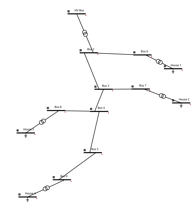
The system features:
9 Buses.
5 Transformers.
4 Loads.
7 Lines.
Solution file of the grid system can be found in GitHub
Step 1: Create a Transformer
Open VeraGrid:
‘Drag and drop’ 2 ‘Bus’ element to the diagram canvas:
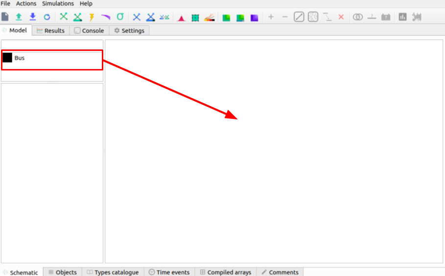
Select (double ‘click’) Bus 0 and change the parameters (on the left side pane):
name |
HV Bus |
|---|---|
Vnom[kV] |
20 |
Select (double ‘click’) Bus 1 and change the parameters (on the left side pane):
name |
Bus 2 |
|---|---|
Vnom[kV] |
10 |
Hover over either bus element, ‘click and drag’ (when there is a cross) to the other bus to create a branch.
![]()
Note: A transformer will be created between HV Bus and Bus 2 when nominal voltage values are different.
Note: The name of an element may not change until you ‘double click’ the element on the diagram canvas after the change.
Step 2: Create Lines of Different Lengths
Create 3 more Buses (Bus 3, Bus 4 and Bus 5) and create a branch between them.
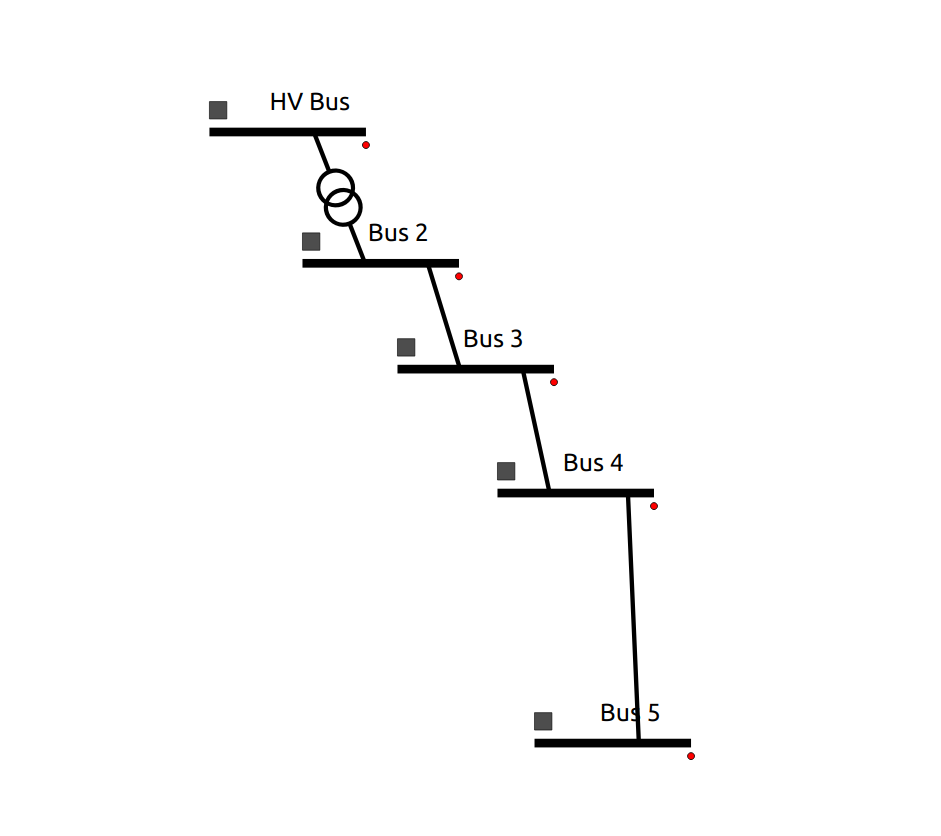
Select the branch between Bus 2 and Bus 3 and change its parameters to:
name |
Line 1 |
|---|---|
length[km] |
5 |
Select the branch between Bus 3 and Bus 4 and change its parameters to:
name |
Line 2 |
|---|---|
length[km] |
3 |
Select the branch between Bus 4 and Bus 5 and change its parameters to:
name |
Line 3 |
|---|---|
length[km] |
7 |
Note: Element placing can be changed by ‘clicking’ the square on the right hand side of a bus.
Step 3: Add More Lines and Buses
Add Bus 6 to the right of Bus 2.
Add Bus 7 to the right of Bus 3.
Add Bus 8 and Bus 10 to the left of Bus 4.
Add Bus 9 and Bus 11 to the left of Bus 5.
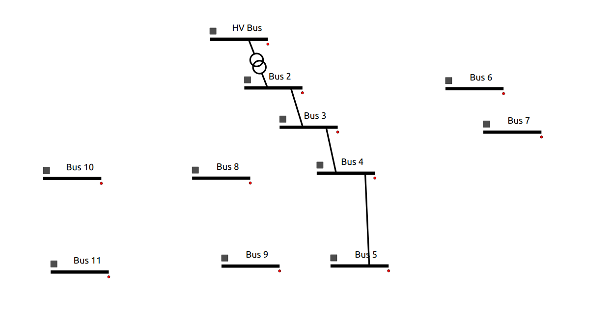
Select the branch between Bus 2 and Bus 6 and change its parameters to:
name |
Line 4 |
|---|---|
length[km] |
2 |
Select the branch between Bus 3 and Bus 7 and change its parameters to:
name |
Line 5 |
|---|---|
length[km] |
1.6 |
Select the branch between Bus 4 and Bus 8 and change its parameters to:
name |
Line 7 |
|---|---|
length[km] |
1.5 |
Select the branch between Bus 5 and Bus 9 and change its parameters to:
name |
Line 8 |
|---|---|
length[km] |
2 |
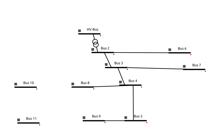
Step 4: Create Loads
Select Bus 10 and change parameters to:
name |
House 3 |
|---|---|
Vnom[kV] |
0.4 |
Create a line between Bus 8 and House 3 (a transformer will be created). Rename it to ‘TR House 3’.
Select Bus 11 and change parameters to:
name |
House 4 |
|---|---|
Vnom[kV] |
0.4 |
Create a line between Bus 9 and House 4 (a transformer will be created). Rename it to ‘TR House 4’.
Right ‘click’ on House 3 and select ‘Add Load’.
Right ‘click’ on House 4 and select ‘Add Load’.
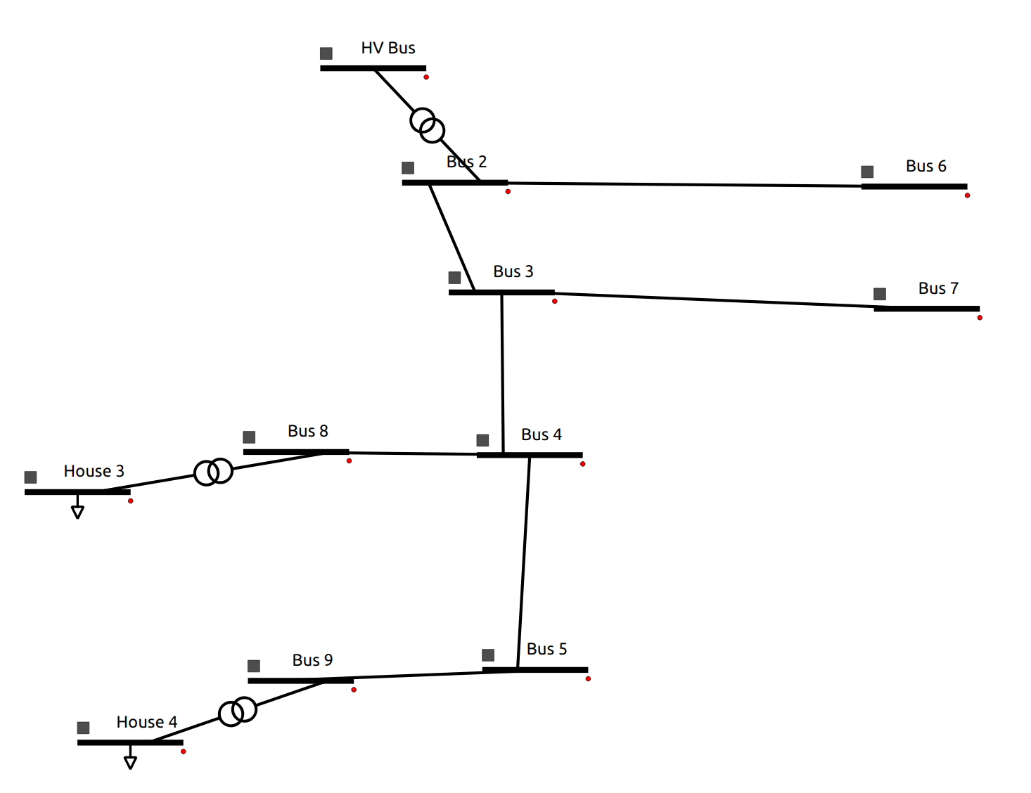
Step 5: Create House 1 and House 2
Create load House 1: Create a new bus and name it ‘House 1’ to the right of Bus 6, and a transformer in the line between Bus 6 and House 1. The parameters are the following:
name |
House 1 |
|---|---|
Vnom[kV] |
0.4 |
Create load House 2: Create a new bus and name it ‘House 2’ to the right of Bus 7, and a transformer in the line between Bus 7 and House 2. The parameters are the following:
name |
House 2 |
|---|---|
Vnom[kV] |
0.4 |
The full system topology looks like:
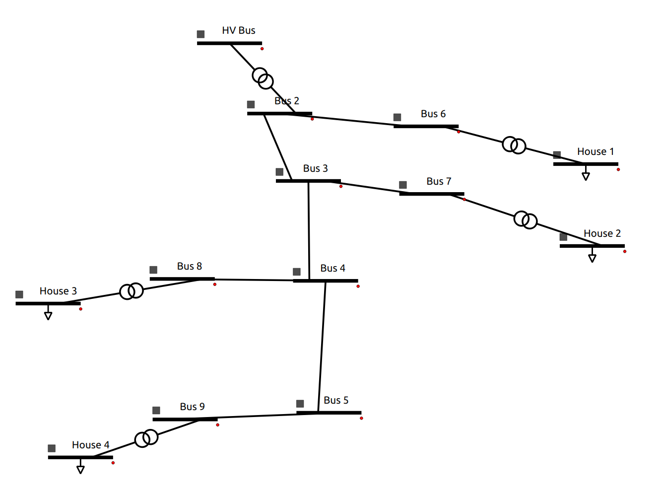
Note: do not forget to add the load after you rename the House buses.
Step 6: Defining the Main Transformer
In order to define the type of transformer a catalogue is available within the VeraGrid repository.
This transformer is the transformer between HV Bus and Bus 2. The transformer is: 25 MV 20/10 kV.
Access the catalogue (Excel file). It can be found in the repository at
VeraGrid/Grids_and_profiles/grids/equipmentand select ‘equipment.ods’.Select the ‘Transformers’ sheet.
Remove all filters on the ‘Rate (MVA)’ column by pressing on the downward arrow.
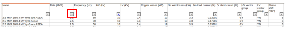
Select the ‘20 kV’ filter on the ‘HV (kV)’ column using the downward arrow.
Select the ‘10 kV’ filter on the ‘LV (kV)’ column using the downward arrow.
The parameters of the transformer are:
name |
25 MVA 20/10 kV |
|---|---|
Rate[MVA] |
25 |
Frequency[Hz] |
50 |
HV[kV] |
20 |
LV[kV] |
10 |
Copper Losses[kW] |
102.76 |
No Load Losses[kW] |
10.96 |
No Load Current[%] |
0.1 |
V Short Circuit[%] |
10.3 |
HV Vector Group |
YN |
LV Vector Group |
D |
Phase Shift |
5 |
Double click on the transformer between HV Bus and Bus 2 and enter the following parameters (based on the model selected):
Sn |
25 |
|---|---|
Pcu |
102.76 |
Pfe |
10.96 |
lo |
0.1 |
Vsc |
10.3 |
Once the parameters are placed, right click and select ‘Add to catalogue’. This way the branch p.u. values are calculated from the template values.
Note: In the new VeraGrid version, a transformer can be defined by just right clicking on the desired transformer and selecting the type from the drop down menu.
Note: All of the element types can be found under the ‘Types catalogue’ tab after clicking on the desired element, then clock ‘Load Values’ to change the parameters.
Step 7: Defining Load Transformers
The transformers used for the 4 loads (houses) a 10 to 0.4 kV transformer will be used. The name is a ‘0.016 MVA 10/0.4 kV ET 16/23 SGB’.
Using the same catalogue find the transformer and do this for the transformer between Bus 6 and House 1.
The parameters of the transformer are:
name |
0.016 MVA 10/0.4 kV ET 16/23 SGB |
|---|---|
Rate[MVA] |
0.016 |
Frequency[Hz] |
50 |
HV[kV] |
10 |
LV[kV] |
0.4 |
Copper Losses[kW] |
0.45 |
No Load Losses[kW] |
0.11 |
No Load Current[%] |
0.68751 |
V Short Circuit[%] |
3.75 |
HV Vector Group |
Y |
LV Vector Group |
ZN |
Phase Shift |
5 |
Fill these values out for the pop up menu:
Sn |
0.016 |
|---|---|
Pcu |
0.45 |
Pfe |
0.11 |
lo |
0.687510 |
Vsc |
3.75 |
Right click on the transformer and select ‘Add to catalogue’ this will create a template for quick add.
Rename the transformer to ‘TR house 1’.
On the lower tabs select ‘Types catalogue’.
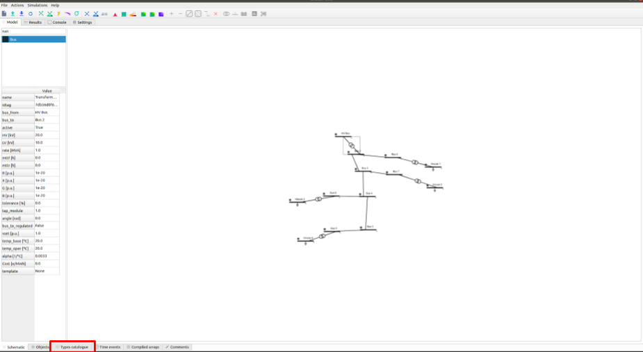
Select the transformer that has the characteristics of the 10 to 0.4 kV transformer and rename it to ‘House trafo’. Now you have defined a transformer type that can be added to many transformers.
Note: In the new VeraGrid version, a transformer can be defined by just right clicking on the desired transformer and selecting the type from the drop down menu.
Step 8: Defining Other Transformers
Now that ‘House trafo’ has been created, other transformers can be set to the same type.
In the ‘Schematic’ tab change the name of the other load transformers to their respective load (i.e. House 3 transformer rename to ‘TR house 3’).
Double click on the transformer
Click ‘Load Values’ to set the parameters.
Repeat for all desired transformers: TR house 3, TR house 4, TR house 2.
Note: this can be done with all elements either to preloaded models or models you create.
Step 9: Defining Wires and Overhead Lines
Just like in Step 7 access the ‘Types catalouge’ and select ‘Wires’.
All of the wire types will show up and select the 17th option ‘AWG SLD’. The parameters are:
R [Oh/Km] |
1.485077 |
|---|---|
X [Ohm/Km] |
0 |
GMR [m] |
0.001603 |
Max Current [kA] |
0.11 |
Note: A new wire or custom wire can be added using the ‘+’ button on the top right.
Now that you have located the wire you will use, in the same tab of ‘Data structures’ select ‘Overhead Lines’.
Click on the ‘+’ sign at the top right to create a new element. A new element ‘0:Tower’ should come up.
Select the element ‘0: Tower’ and click on the pencil on the top right corner to edit. A new window should pop up.
Rename the overhead line to: ‘Distribution Line’.
Select the wire ‘AWG SLD’, highlight it and click on the ‘+’ sign on the ‘Wire composition’ section below:
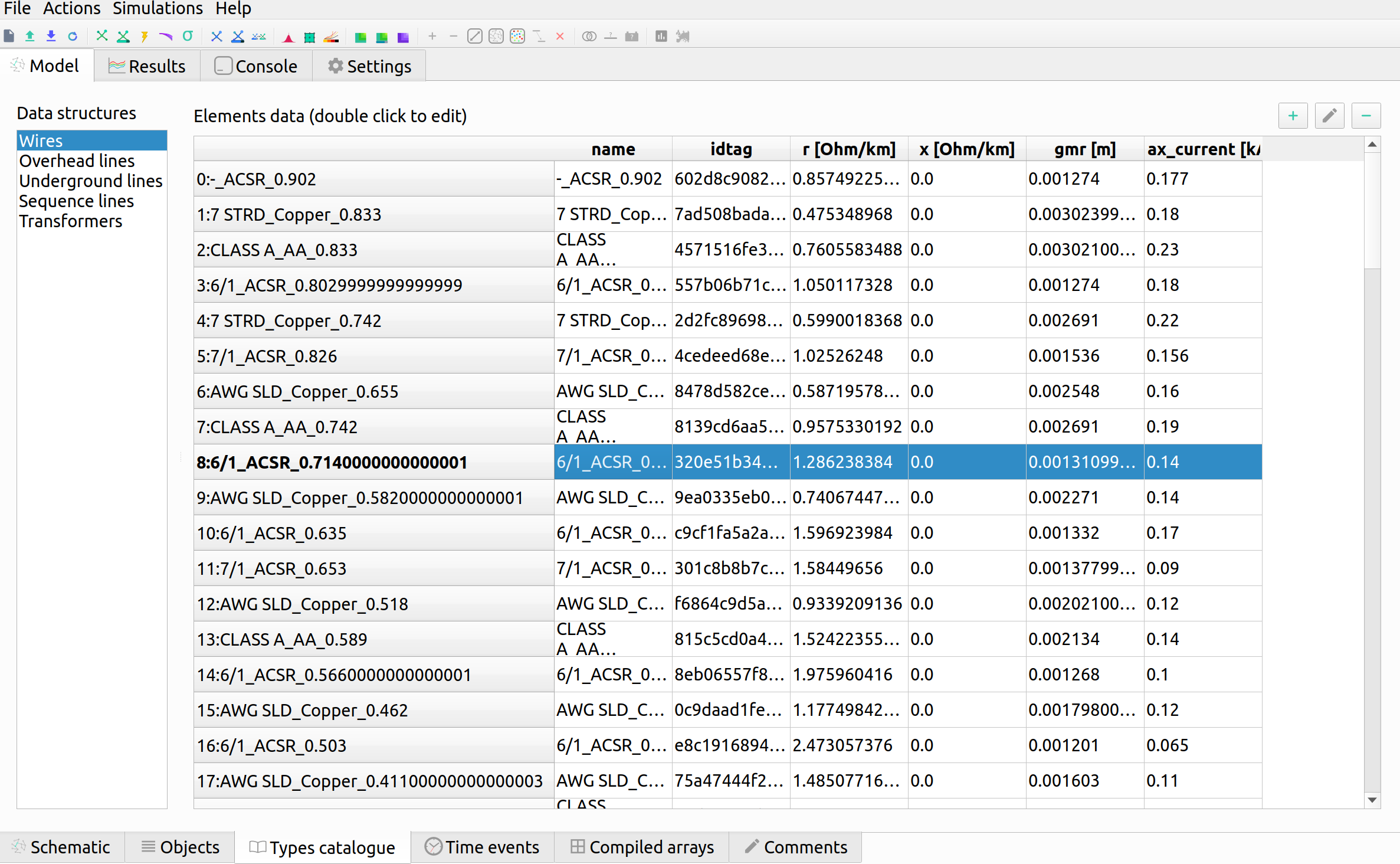
Add the ‘AWG SLD’ wire three times to enter the wire arrangement. The formulas come from ATP-EMTP.
Give each cable a different phase: 1, 2 and 3. Enter the following parameters for Phase 2 and Phase 3.
Wire |
X[m] |
Y [m] |
Phase |
|---|---|---|---|
AWG SLD |
0 |
7.0 |
1 |
AWG SLD |
0.4 |
7.3 |
2 |
AWG SLD |
0.8 |
7.0 |
3 |
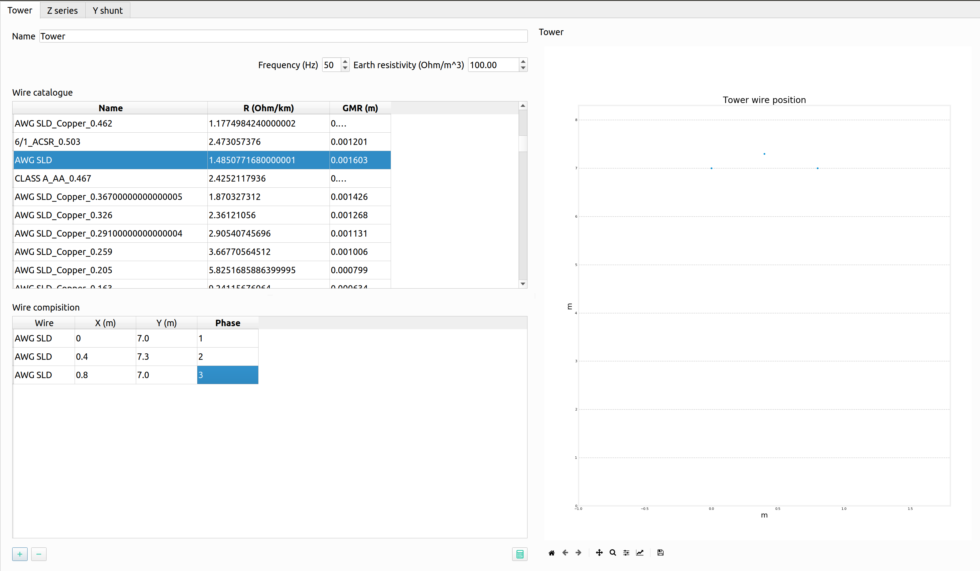
Click on the ‘Compute matrices’ button the little calculator on the bottom right and you will be able to see:
-Tower Wire Position (right).
Z Series [Ohm/Km] for ABCN (under the ‘Z series’ tab at the top).
Z Series [Ohm/Km] for ABC (under the ‘Z series’ tab at the top).
Z Series [Ohm/Km] for the sequence components (under the ‘Z series’ tab at the top).
Y shunt [uS/Km] for ABCN (under the ‘Y shunt’ tab at the top).
Y shunt [uS/Km] for ABC (under the ‘Y shunt’ tab at the top).
Y shunt [uS/Km] for the sequence components (under the ‘Y shunt’ tab at the top).
Close the window, and your ‘Elements Data’ tab should look lie:
To apply this model to the lines in the model: In the ‘Schematic’ tab change the name of the other load transformers to their respective load (i.e. House 3 transformer rename to ‘TR house 3’).
Double click on the desired line. Click ‘Load Values’ to set the parameters.
Repeat for all desired lines. In this case Line 1 to Line 8. The ‘Objecs -> Line’ Data tab should look like:
Note: this can be done with all elements either to preloaded models or models you create.
Step 10: Importing Load Profiles
Head to the ‘Time Events’ tab on the bottom part of the GUI. Then click on the left and select ‘Import Profiles’. This should bring up the ‘Profile Import Dialogue’ box.
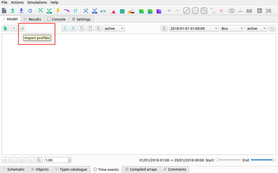
Note: Make sure that the desired object is set to ‘Load’ and power types are both set to ‘P’.
Click on ‘Import file’ box on the left. This will bring up a file explorer tab.
In the installation location head to ‘…/VeraGrid/Grids_and_Profiles/profiles/…’ then select the Excel file called: ‘Total_profiles_1W_1H.xlsx’.
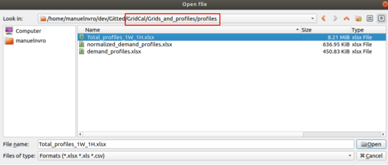
On the next dialogue box select ‘Sheet 1’ and ‘OK’. Wait for all the profiles to load.
Any load profile can be selected. For example, click on ‘USA_AL_Dothan.Muni.AP.7222268_TMY3_BASE(kW)’. Then select the ‘Plot’ tab to see the load profile in kW for January 2018.
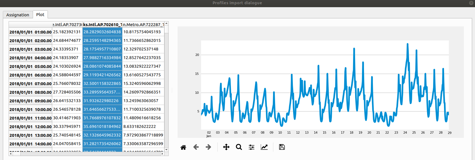
Note: in the ‘Assignation’ tab, the units can be changed to: T, G, k , m Watts.
Set the units to ‘k’.
On the right, you can see the different ‘Objectives’, fill the out by double-clicking on a profile and then double-clicking in the ‘active’ box of the desired ‘Objective’. The profiles are assigned as follows:
Load@House 1: ‘USA_AL_Muscle.Shoals.Rgni.AP.723235_TMY3_BASE(k@)’.
Load@House 2: ‘USA_AZ_Douglas-Bisbee.Douglas.intl.AP.722735_TMY3_BASE(k@)’.
Load@House 3: ‘USA_AL_Tuscaloosa.Muni.AP.722286_TMY3_BASE(k@)’.
Load@House 4: ‘USA_AL_Birmingham.Muni.AP.722286_TMY3_BASE(k@)’.
The selection should look like this:
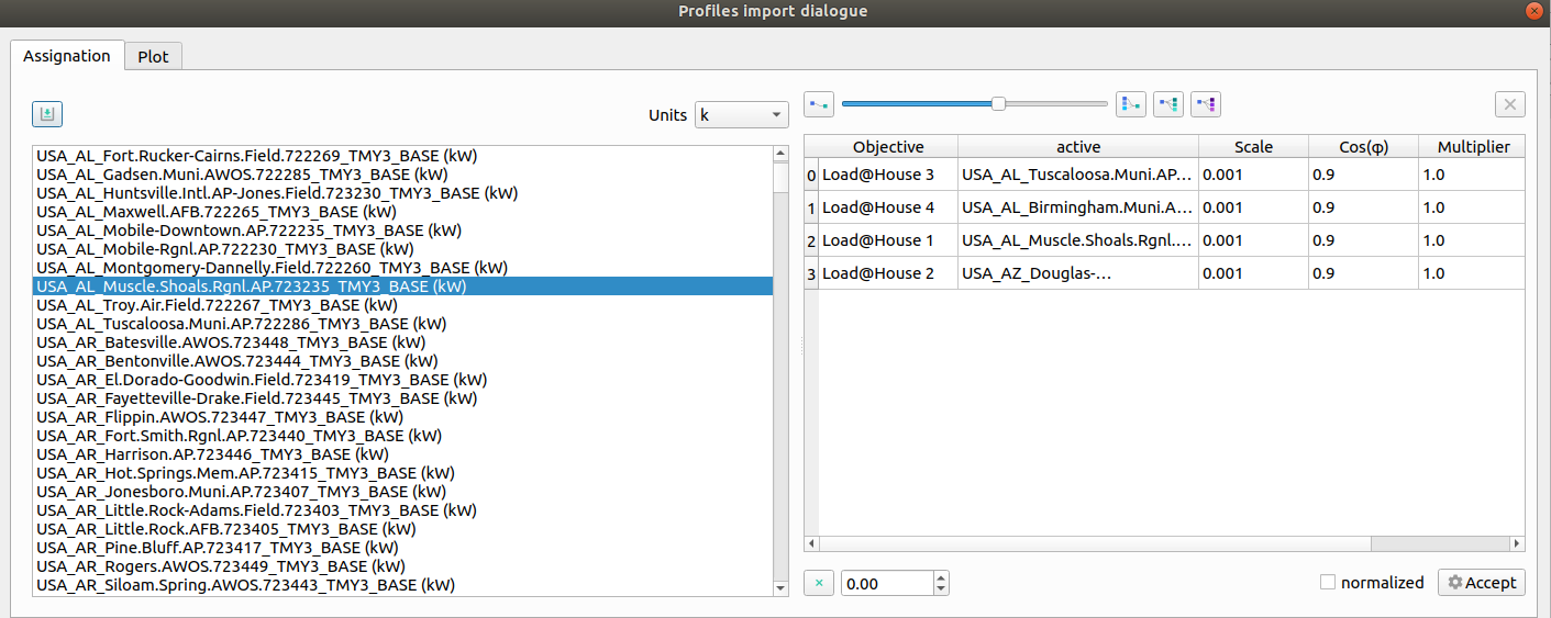
Click ‘Accept’ to load the profiles.
On the ‘Time events’ tab, confirm that the time series has bene added:
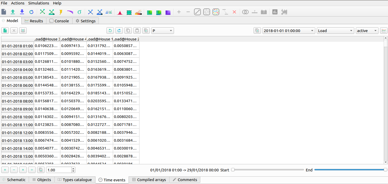
To set the reactive power as a copy of the active power and scale it, click on the dropdown menu and select ‘Q’. Then click next to it on the ‘Copy the selected profile into the profiles selected next to this button’ button. When the pop up box comes on confirming the action select ‘Yes’.
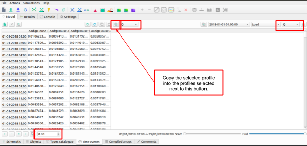

On the bottom left side scale it by 0.8 and click on the multiply button. The profile should look like this:
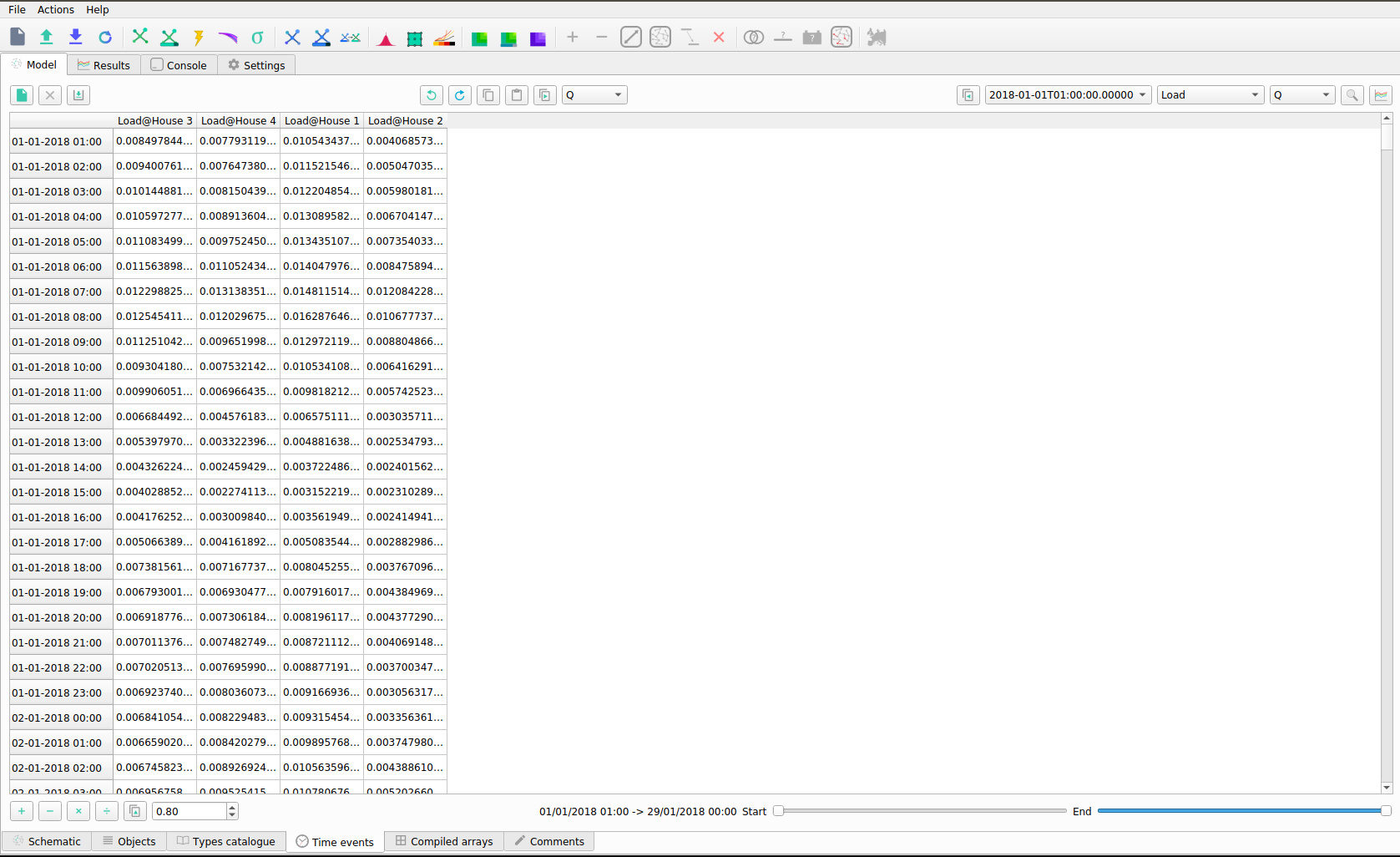
The profiles can be visualized by 1) selecting the times, and load, and clicking on the ‘Plot the selected project’s profile’ button.
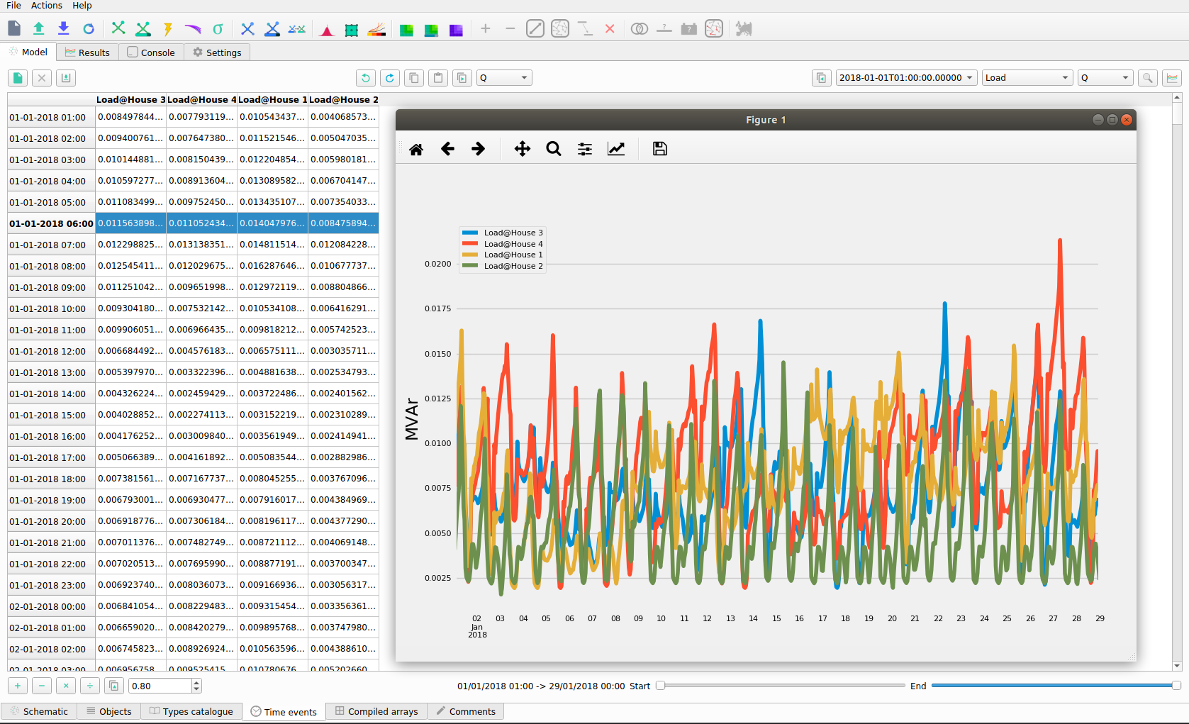
Power flow snapshots can be seen also by going to the ‘Time events’ tabs, and then
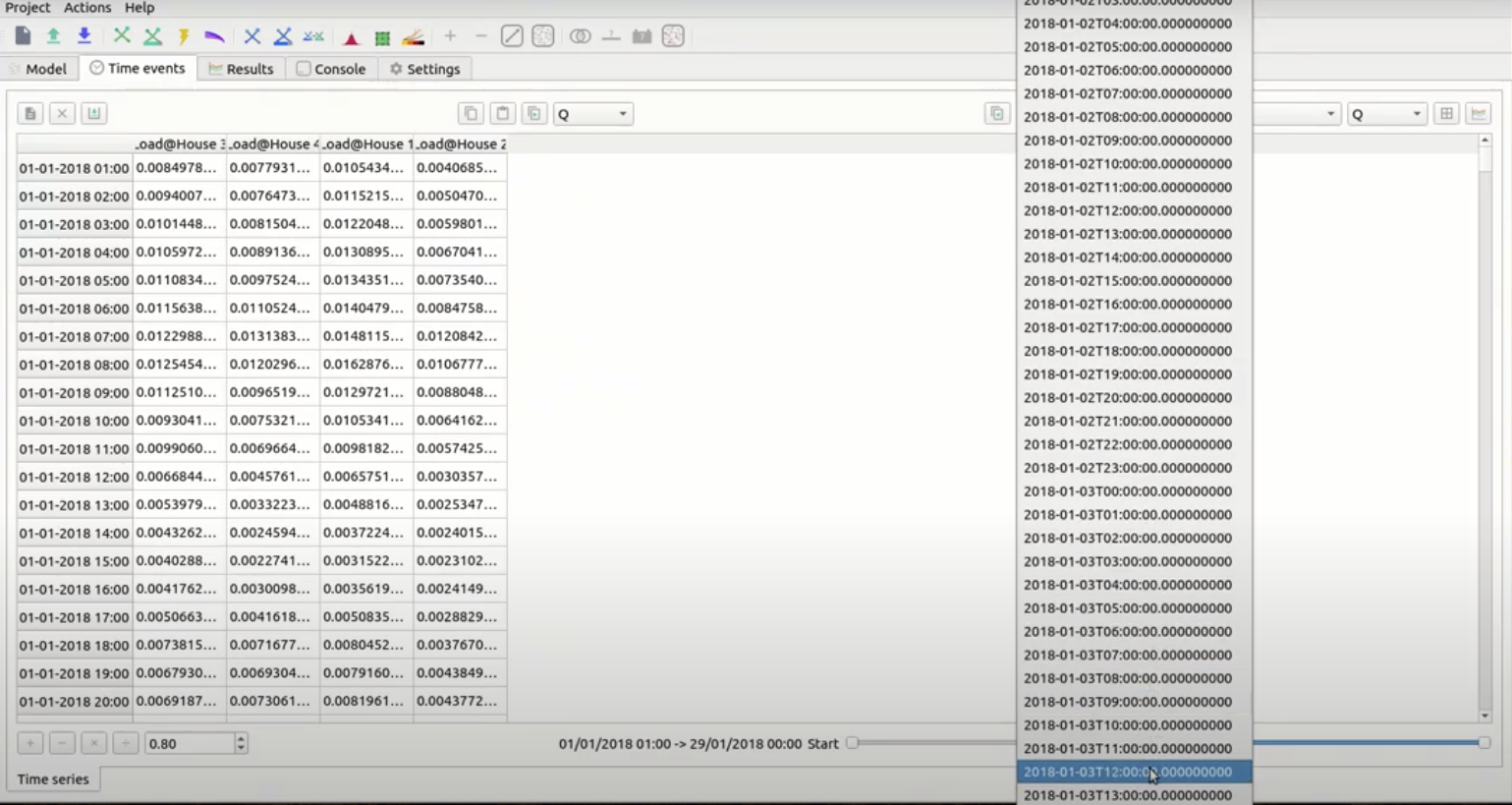
Step 10: Set Power Flow From A Profile
Once we have checked that the profiles are okay, we can set the power flow snapshot from the profiles and run a power flow.
Head to the ‘Time Series’ Tab and select ‘2018+01-03T12:00:00.00000000000000’.
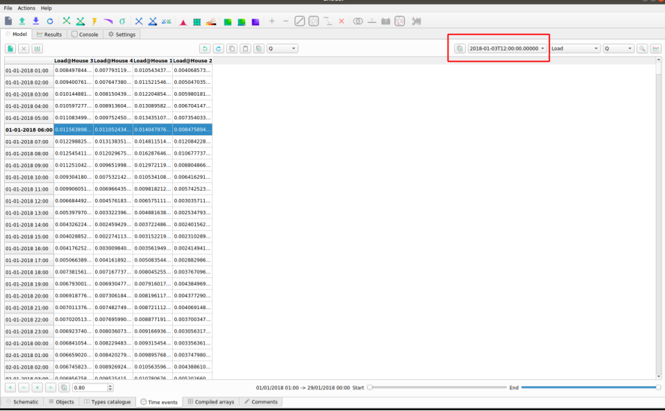
Select the ‘Assign selected values to the selected time slot to the grid’.
Select ‘Yes’.
Step 11: Running a Power Flow
In order to run the power flow, we must select the slack bus. If you try run without one, you will get this error message:
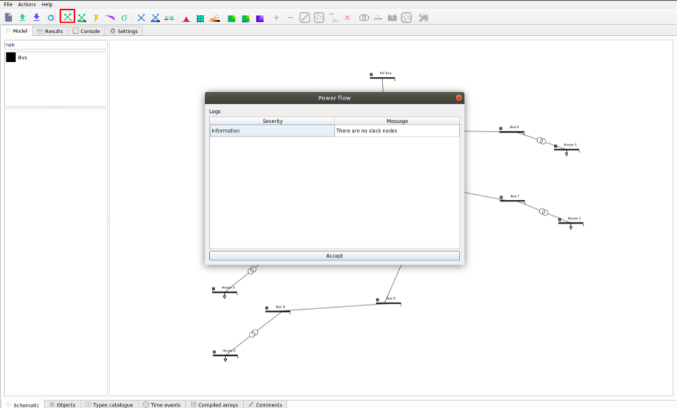
Note: to run a Power Flow, select the ‘Power Flow’ button in the red square in the figure above.
Return to the ‘Schematic’ tab.
Select the ‘HV Bus’.
On the left pane, select ‘True’ in the ‘is_slack’ option.
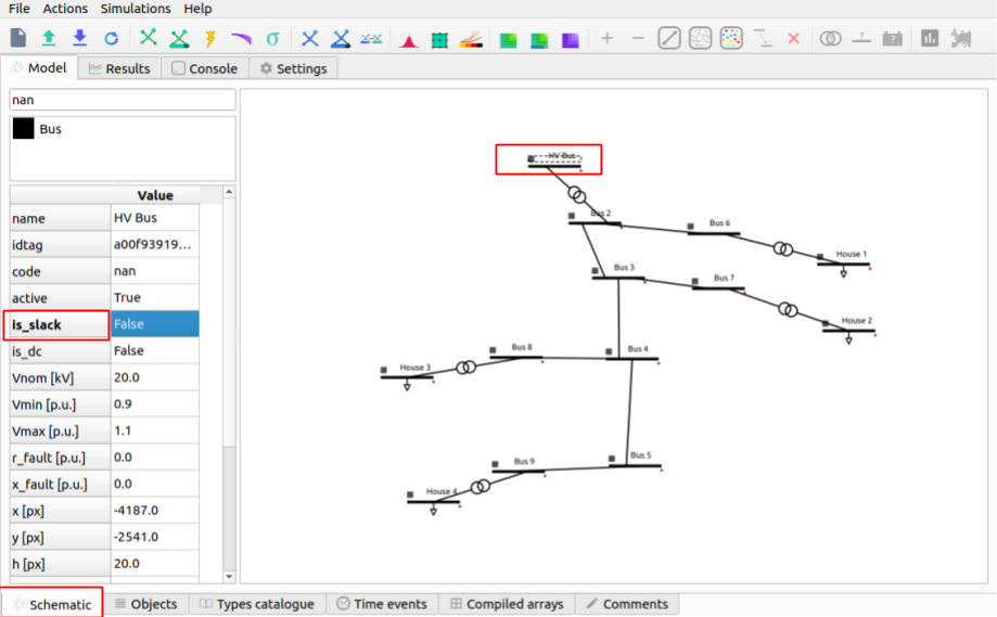
Click on the ‘Power Flow’ button and the grid will be colored according to the voltage or loading.
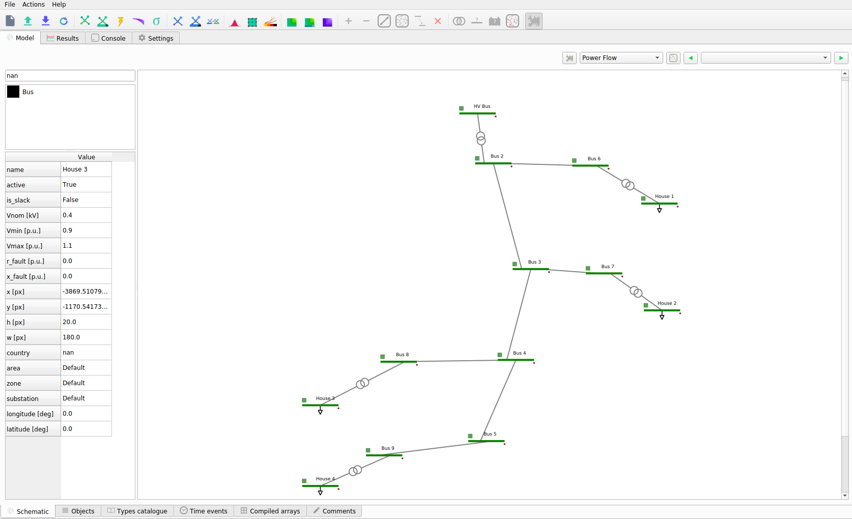
Click on the ‘Power Flow Time Series’ button and the grid will be colored according to th
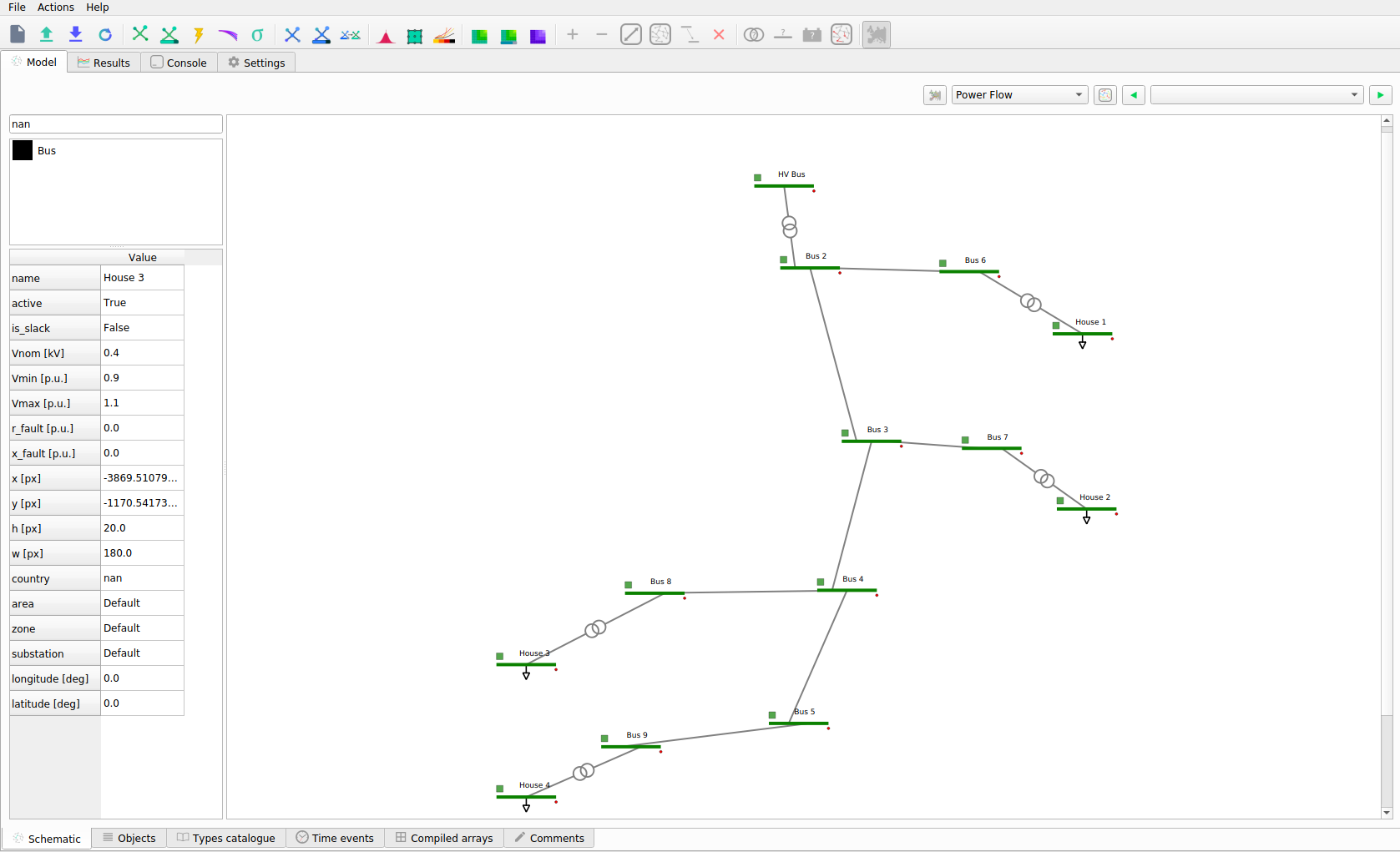
In addition by hovering above a transformer you can see the loading percentage and the power.
![]()
Step 12: Results & Features
Here are some of the few results and features that are available with VeraGrid. All results can be found in the ‘Results’ tab. Here you can see a list of all studies perfomed and their respective results:
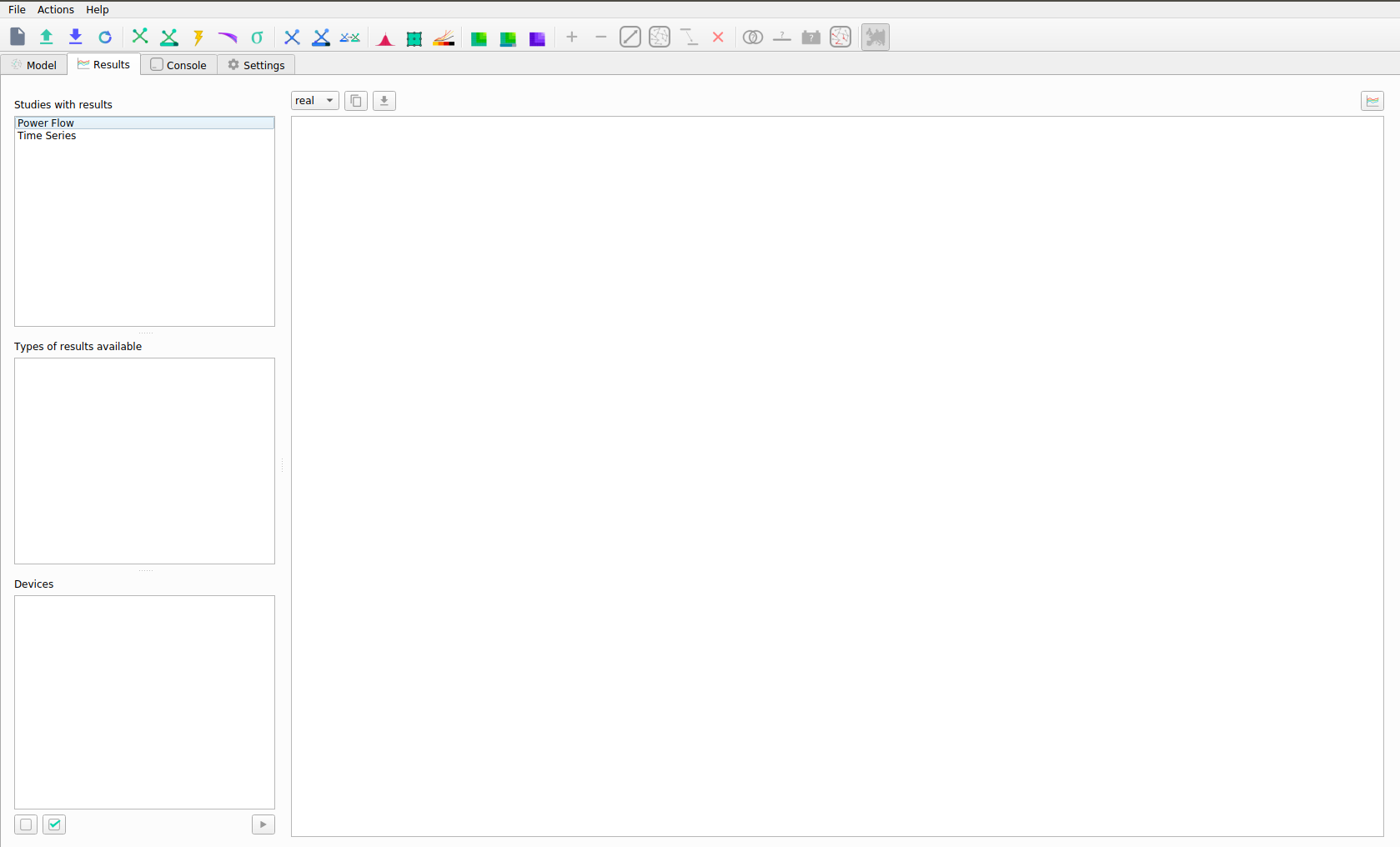
In the results you can also choose from:
Study
Result Type
Devices
From here you can choose and customize the plot and results that are displayed to you.
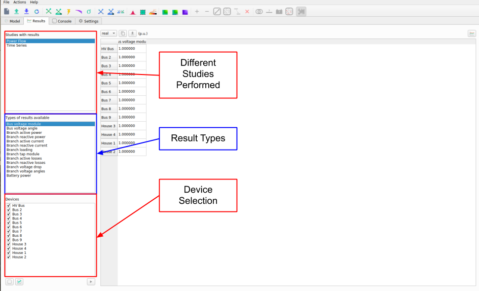
Select the Study, Result Type and Devices, then the Data will pop up in table format, to graph it use the ‘Graph’ button on the top right. The graph will come up on a new figure:
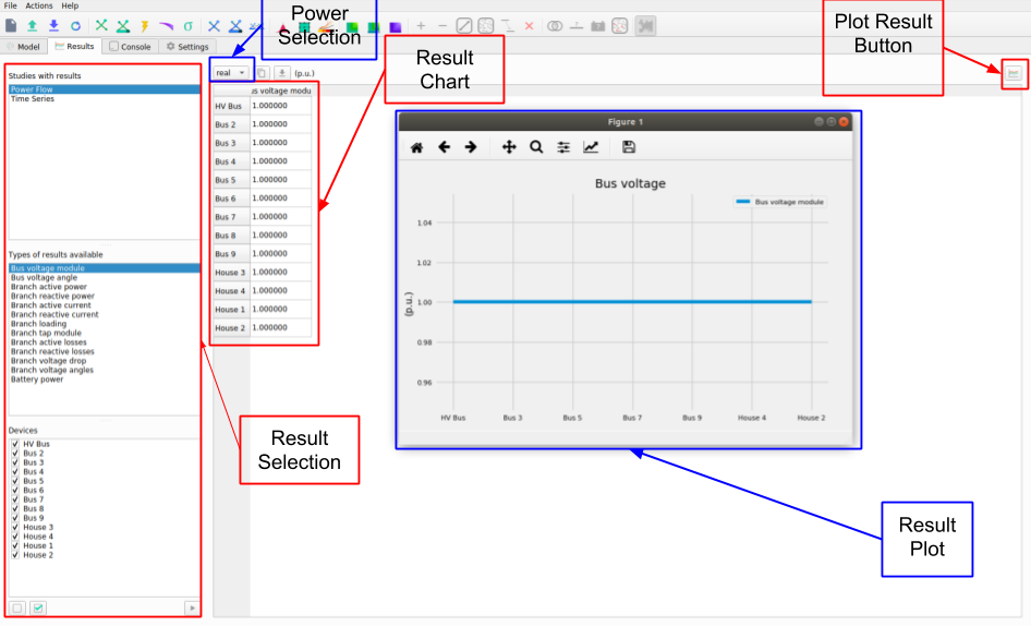
In the ‘Schematic’ Tab, you can visualize the result’s profiles, by selection the load, right click and selecting ‘Plot Profiles’:
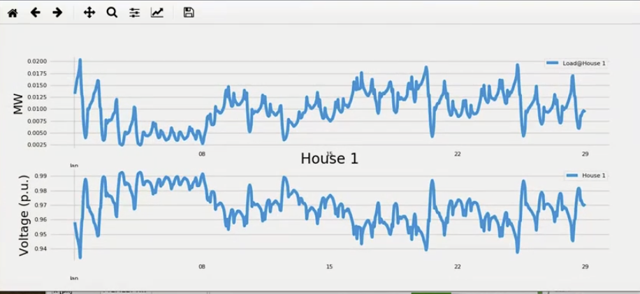
From the result plots you can do various things with the plot:

Power Flow on the 5-Node Example Grid
This example creates the five-node grid from the fantastic book “Power System Load Flow Analysis” and runs a power flow. After the power flow is executed, the results are printed on the console.
import VeraGridEngine.api as gce

# declare a circuit object
grid = gce.MultiCircuit()

# Add the buses and the generators and loads attached
bus1 = gce.Bus('Bus 1', Vnom=20)
# bus1.is_slack = True  # we may mark the bus a slack
grid.add_bus(bus1)

# add a generator to the bus 1
gen1 = gce.Generator('Slack Generator', vset=1.0)
grid.add_generator(bus1, gen1)

# add bus 2 with a load attached
bus2 = gce.Bus('Bus 2', Vnom=20)
grid.add_bus(bus2)
grid.add_load(bus2, gce.Load('load 2', P=40, Q=20))

# add bus 3 with a load attached
bus3 = gce.Bus('Bus 3', Vnom=20)
grid.add_bus(bus3)
grid.add_load(bus3, gce.Load('load 3', P=25, Q=15))

# add bus 4 with a load attached
bus4 = gce.Bus('Bus 4', Vnom=20)
grid.add_bus(bus4)
grid.add_load(bus4, gce.Load('load 4', P=40, Q=20))

# add bus 5 with a load attached
bus5 = gce.Bus('Bus 5', Vnom=20)
grid.add_bus(bus5)
grid.add_load(bus5, gce.Load('load 5', P=50, Q=20))

# add Lines connecting the buses
grid.add_line(gce.Line(bus1, bus2, name='line 1-2', r=0.05, x=0.11, b=0.02))
grid.add_line(gce.Line(bus1, bus3, name='line 1-3', r=0.05, x=0.11, b=0.02))
grid.add_line(gce.Line(bus1, bus5, name='line 1-5', r=0.03, x=0.08, b=0.02))
grid.add_line(gce.Line(bus2, bus3, name='line 2-3', r=0.04, x=0.09, b=0.02))
grid.add_line(gce.Line(bus2, bus5, name='line 2-5', r=0.04, x=0.09, b=0.02))
grid.add_line(gce.Line(bus3, bus4, name='line 3-4', r=0.06, x=0.13, b=0.03))
grid.add_line(gce.Line(bus4, bus5, name='line 4-5', r=0.04, x=0.09, b=0.02))

results = gce.power_flow(grid)

print(grid.name)
print('Converged:', results.converged, 'error:', results.error)
print(results.get_bus_df())
print(results.get_branch_df())